Telemetrie via Audiokanal - Programmierer und Tester gesucht

Status
Nicht offen für weitere Antworten.

QuadMax

Erfahrener Benutzer
#1
Es gibt Lösungen für Telemetrie und Tracking via Audiokanal , aber bis jetzt hat mich keine richtig überzeugt.
Nimmt man einen kleinen IC braucht man noch das ganze drumherum...
Meine Idee war es so etwas für den Arduino zu programmieren, den gibts schon billig und vor allen Dingen fertig zu kaufen.
Seit kurzem Diskutiere ich mit einem Programmierer über die Realisierung. Seine Seite findet ihr hier.

Das ganze auch für den Arduino verfügbar zu machen ist nicht ganz so einfach und übersteigt auch meine Programmierkünste ein bisschen.
Ich habe ihm aber versprochen hier mal auf deutsch anzufragen.

Daher meine Frage:
Hat jemand von euch Lust mit ihm / (uns :)) so eine DIY Telemetrie zu entwickeln?
Gibt es mutige ;) Tester die dann das ganze Testen könnten?

Das Ziel wäre es, das das Modem Telemtriedaten übertragen kann (auch für Antenntracking geeignet). Das ganze soll auf zwei Arduinos aufbauen, z.B.: zwei pro minis.

Wir müssen nicht von Null anfangen, denn Mark hat das ganze schon fertig für den avr, allerdings noch nicht als Library für die Arduino IDE.
Wer gerne helfen möchte, der melde sich bitte kurz zu Wort, dann kann ich ihn gerne auf den neusten Stand bringen.
Wer helfen will aber keinen Ardu hat, dem kann ich gerne zwei pro minis kostenlos zuschicken.


Gruß Max
 

Icesory

Magic-Smoke liberator
#2
Also ich arbeite schon ein paar Jahre mit Atmel und habe da gewisse Erfahrungen. Arduino habe ich erst dieses Jahr angefangen, finde ich aber nicht so toll. Ist mir zu viel virtualisiert.

An eine Daten Übertragung per Audio habe ich auch schon gedacht. Dabei interessiert mich vor allem was für Hardware benötigt wird.
Eigentlich sollte es doch reiche einen UART TX mit dem Audio Eingang zu verbinden und am Empfänger dann halt den RX.

Ich wollte es bidirektionale machen um Daten auch wieder in den Flieger zu bekommen. Das dann aber mit der Fernbedienung. Also ein Kanal der Funke überträgt dann Informationen zum Flieger.

Erzähl mal mehr wie und was ihr genau macht.
 

QuadMax

Erfahrener Benutzer
#3
An eine Daten Übertragung per Audio habe ich auch schon gedacht. Dabei interessiert mich vor allem was für Hardware benötigt wird.
Eigentlich sollte es doch reiche einen UART TX mit dem Audio Eingang zu verbinden und am Empfänger dann halt den RX.


Erzähl mal mehr wie und was ihr genau macht.
Hi Icesory,

Leider reicht es nicht einfach einen UART TX mit dem Audio Eingang zu verbinden. Auf dem Gebiet bin ich aber kein Spezialist. Einige würden mich jetzt steinigen wenn ich mein gefährliches Halbwissen verbreite ;)
Google einfach mal nach Frequenzmodulation.

Als Hardware sollen nur zwei Ardus verwendet werden, vielleicht ein Pro Mini (klein und leicht) oder ähnliche.

Mark (Erfinder des Micromodems) hat schon angefangen das ganze für den Ardu nutzbar zu machen. Wenn er seinen ersten Code fertig hat, dann melde ich mich wieder, oder er schreibt selbst nen Post :).

Gruß Max
 

Icesory

Magic-Smoke liberator
#4
Also eigentlich ist das wirklich einfach umzusetzen.
Man muss nur zwei töne definieren. Der eine ist halt eine 1 und der andere eine 0. Dann bestimmt man eine Baudrate die unter der Abtastfrequenz des Audiosystems liegt und schiebt dann nach und nach die daten raus.

Alternativ könnte man einen MT8880 IC nehmen. Der kann echtes DTMF dann halt mit mehreren Frequenzen parallel.
http://www.conrad.de/ce/de/product/...haeuseart-DIP-20-Ausfuehrung-DTMF-Transceiver

http://www.wolfgang-back.com/PDF/MT8880C.pdf
 
Zuletzt bearbeitet:
#5
Hi guys and girls!
Sorry for writing in english, but my german skills are not so good ;) I am the developer of MicroModem, which is a 1200bps AFSK data modem using Arduino hardware. As Max already stated, while this is using the ATmega328p found on Arduino boards, it is not programmed in the Arduino environment, and thus is hard to integrate with Arduino based projects.

While the concept is simple as you say Icesory, it is not so easy to implement correctly. It takes very precise timing and effecient code to run the modulation and demodulation correctly. Even though the data rate is 1200bps, we run the sampling at 9600 hz. This is already just above what the Arduino is capable of, but with some tweaks, it is possible and works very well.

When Max contacted me about the possibilities for using it as a telemetry link, I found the project very interesting, and decided to give it a shot and see what it would take to port my work to an Arduino library.

I have worked a bit on this for two days now, and the good news is that I have ported the data modulation and demodulation to an Arduino library. This testing library is now functional for sending and receiving data over an audio channel :) This means that if there is interest in the project, and a few people willing to help with testing it, I will happily commiit to creating a full-featured Telemetry library. I think it is a really useful and interesting project! Luckily I have a quadcopter and FPV kits myself, so I am not totally in the dark. Let me know what you guys think!

Cheers, Mark
 
#6
Also, I thought I'd write what is needed to make this work hardware wise. I designed the software and hardware to be as simple as possible, and this is what you need to make a fully functional data transmitter or receiver:

For a transmit only modem:
- An Arduino with an ATMega328p or compatible chip
- 7 simple components: (5 resistors, 2 capacitors)

For a transmit and receive modem:
- An Arduino with an ATMega328p or compatible chip
- 10 simple components: (7 resistors, 3 capacitors)

With this simplified setup, it is possible to just insert the components directly into the ports on the Arduino and tie them together, no PCB or soldering is required. Although it's probably a good idea to solder it if it's' going to fly ;)
 

cesco1

Erfahrener Benutzer
#7
Intresting project.

I had a peek at the modem source, the demodulator part, but i did not find a description of the demodualtion process. Can you elaborate on the "Delayed FIFO for frequency discrimination" ?

Btw i have the same baofeng handy :)
 
Zuletzt bearbeitet:
#8
Hi Cesco!
It's not quite as simple as that unfortunately. Hold on to your hats, this is going to be a little technical ;) It works something like this:

- Take a sample of the baseband audio 9600 time each second (1200 bps * 8 samples per bit = 9600)

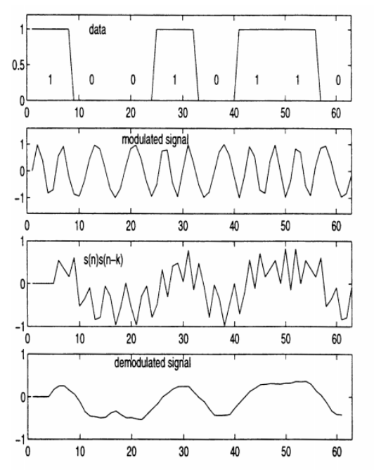
- For the current audio sample, multiply it by the sample taken 4 samples ago. What this acheives is basically a very simple fourier transform that tells us the frequency component of the received sample. Why do we multiply with the sample 4 samples ago? This is the delay that is needed to discern between the particular frequencies we are looking at (1200Hz and 2200Hz). This kind of fourier transform cannot tell us any other frequency components than exactly the one the delay is "tuned" to. But it is very fast! That means, that if the result of the transform is larger than zero, we detect this as a logical 1, and if not, we detect a logical 0.

- We now take these logical ones and zeroes and feed them into a delay line (remember, we have 8 samples, aka 8 logical bits per _encoded_ bit). When our 8-bit long "sampling window" is full, we look at the logical bits inside this sampling window to determine whether we actually received a 1 or 0 encoded bit.

- Now, it is important to remember that an encoded bit is not the same as a data bit! We are using NRZ-encoding, which means that every time the value of the encoded bits transitions, we have a 0 data bit! If the encoded bits stays the same, we have a 1 data bit.

- Now that we have figured out the actual data bits, we pass these on to an HDLC parser. The High-level Data Link Control parser is responsible for assembling the received bits into bytes, and for detecting start and end of transmission. (This is theoretically a Layer 2 protocol, responsible for "framing" data packets). The HDLC parser looks for frame (packet) start and end flags, and for control signals, and a few other things I wont go into detail with here.

- The HDLC parser then pushes the actual data on to a Layer 3 protocol, responsible for delivering the data inside the frames to a program, an application, or a higher level protocol yet.

- This Layer 3 protocol is then responsible for checking that the data packets were received without error, or if there was errors, to try and correct them.

There's a few more details to it than that, but that is what is happening in general terms.

Seen in that light, the status of the work for the Arduino library I'm currently working on is as follows:

- The modulation and demodulation code has been ported to the library.
- The HDLC parser has been ported to the library.
- This means that currently, the library offers an uncorrected, unreliable, but functioning data link between two points, over an audio channel.

Now the work needs to be done to create a Layer 3 protocol, that can transport the data in a more reliable way, which means that it should include good error correction functionality. Why is this necessary? Because radio communication is unreliable. If one was to just send out two tones, one signifying 0 and the other 1, without all the "jumping through hoops" I have described here, there is only two options: Receive garbage and nonsense, or go veeeeery very slowly! 1200bps is close to the theoretical limit for a _narrow_ audio channel (and the capabilities of the arduino), so going at this "high" speed, the modulation, demodulation and encoding needs to be designed carefully to actually work! Of course, I did not invent any of the theory behind this, I just wrote an implementation of it :)
 
Zuletzt bearbeitet:

cesco1

Erfahrener Benutzer
#10
Ty Mark. I will have to study that demodulation thing. Might take a while.

This method is more intuitive for me:


Edit:
Yes i think i understand it now.
9600 / 1200 = 8 -> 4 samples delay equals 1/2 wavelength. S * S-delayed = negative
9600 / 2200 = 4,36 -> 4 samples delay is nearly 1 wavelength. S * S-delayed = positive
Would using 1200/2400 hz not give better results?
 
Zuletzt bearbeitet:
#11
I agree, it seems more simple, but it is also an analog method, which means you need to implement the mixers, filters and detectors in analog hardware. That will turn out more complex :) For that solution you mention, you need two good analog frequency synthesizers (it's hard to build a stable and precise sinewave-oscillator to be small enough to fit on an Arduino), two singal mixers and two filters and detectors. Quite a bit of hardware! Or it can be implemented totally in software, but then you need a lot of resources, both memory and processing power, which is just not available on a small microprocessor.

If you can come up with a efficient way of doing this in software, it would be very interesting and cool!
 

cesco1

Erfahrener Benutzer
#12
I did a simulation and this stuff works really well (messed up filter and guessed params)
http://imgur.com/Awz9SoT

The 2 mixer / 2 filter thing is software not hardware. Using IQ mixers we can shift signals down to zero hertz and still know the magnitude. But yes, this might exceed the 328 capability.
 
Zuletzt bearbeitet:
#13
Nicely done! It looks very effective! But yeah, it will be way too much for the small processor to handle, I promise you :D Maybe, if someone can come up with a very effecient, integer implementation it could work, but I doubt it. Either way, that method be easier if implementing a receiver running on a standard computer!
 

cesco1

Erfahrener Benutzer
#14
If your arduino library is opensource i would like to give it a try.

I dont think telemetry needs any error correction. Just a checksum to discard corrupt data. No FEC.
I also think messages should be rather short. The shorter the better :)

BTW
the simulation above is of the s(n)*s(n-k) method. I have to do such things to understand how it works.

Edit:
I did find this very sensitive to input DC offset. Do you compensate in any way?
 
Zuletzt bearbeitet:

QuadMax

Erfahrener Benutzer
#15
Math is really cool

I have made some thoughts about a efficient way for a sinus wave generator.
Perhaps the Taylor series is helpfull here.

What we are doing here is to re-built the sinus wave.
Actually we only need the function from -pi/2 to pi/2 (the rest we could get with a simple for loop from -pi/2 to pi/2 and then go back to -pi/2).

The green one is this function: g(x) = x - 1 / 6 x³ + 1 / 120 x⁵ - 1 / 5040 x⁷
The black one is this function: g(x) = x - 1 / 6 x³ + 1 / 120 x⁵
The red one is this function: sinus(x)

The blue one indicates the difference of the sinus wave and the black function.
The other black function(the one that look very similar to the blue) indicates the difference of the sinus wave and the green function. Both of them have the factor 100 to make the difference nicely readable.

The differnce from the sinus wave to the green function at pi/2 is 0.000156899.
From the black function to the sinus wave we have a difference at pi/2 from: -0.004524856.
That is really small ;) To save resources we could save 1/6 and the other constants that we dont need to calculate it for new x.

I dont know what you mean cesco1 with the s(n)*s(n-k) method, the same?

Best Regards
Max
 

Anhänge

cesco1

Erfahrener Benutzer
#16
s(n)*s(n-k) is the receiver Mark uses. Mark has a pretty good description on how it works some posts ahead.

About the sin thing, i dont know anything about (difficult) math. But let me share some thoughts. Marks modem uses a 512 long (512/4 actually) lookup table for sin. This is way faster than any calculation. And since the DA is only 4 bits, precicision doesent really matter at all. This table size can be significantly reduced. Input sampling is 9600 samples/sec, so output can be the same 9600. Lowest freq is 1200hz, means at 9600 we need a sin lookup table of only 8 elements. Now 2200hz at 9600 doesent match, but going to 2400hz we got a match (4 ele sin table). As bonus the receiver works better with 1200hz / 2400hz than with original values.
 

dd8ed

Erfahrener Benutzer
#17
Hi all,
would an FSK-modem not be simpler as an AFSK-modem ?
This would avoid the complex discrimination and generation of the mark- and space frequencies and leave room for a channel coding in order to operate in a noisy environment and reducing the workload for the processor.
I did a very coarse simulation for a simple fsk-system using an 11-bit barker-code for channel coding and the results, even without any attempt to optimize the parameters look promising. It needs only a 4-times oversampling and the complete math can be of the type integer.
The problem ist that I´m not able to code that for a microcontroller. The simulation is written in VEE (which is propably a very uncommon tool for this purpose)

Just my 2 cents
 

dd8ed

Erfahrener Benutzer
#19
Like all other FM-transmitters for data transmission too. I.e. like your R/C.
What is the problem ?
 

cesco1

Erfahrener Benutzer
#20
Ich kann mir vorstellen dass ein audiokanal ausgelegt für 200hz - 3khz selbst für einfachste FSK RC ppm signale ungeeignet ist. Probiers mal. Deine verwirrung stammt vielleicht vom SSB betrieb, wo beim Sender AFSK reingeht und hinten FSK rauskommt. Wir haben hier aber einen FM sender. Und im unterschied zu deiner alten 35mhz FM RC funke ist das hier ein AC gekoppelter audiokanal.

Ich seh da noch 2 weitere schwachpunkte mit dem barker-code. Aber probiers mal.

Einen entsprechenden signalgenerator mit pc-oszi gibts beimn chinesen für unter 100 eur. http://www.goodluckbuy.com/isds205b-2ch-digital-oscilloscope-20m-virtual-oscilloscope-spectrum-analyzer-data-recorder-dds-sweep.html
 
Zuletzt bearbeitet:
Status
Nicht offen für weitere Antworten.
FPV1

Banggood

Oben Unten