Parasitic elements are a great (and usable) way to get size/gain benefits out of antennas in which traveling and/or standing waves form. Why they haven’t caught on in the FPV community can only be because of the construction cost/complexity they add – but, as KondorFPV has demonstrated for himself, and others like IBCrazy, it has to be well within their skill set.
As many FPV flyers will know and will have experienced, in multi-path reception environments an out-of-phase, or 2nd received/reflected video signal can severely mess up the quality of demodulated video on a monitor (the closer the 2nd received signal is to 180degrees out of phase with the primary or first received video signal, the greater the amount of signal cancellation or interference one is likely to experience) – well, this same traveling/standing wave principal in reverse , which KondorFPV has made use of, can be exploited using a parasitic element to increase gain in most traveling wave type antennas of resonant dimensions, or recover gain lost when dimensions (such as length and/or volume) are reduced for whatever reason.
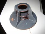
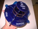
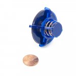
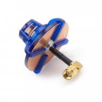
In very simple terms the parasitic element interacts with the phase position (i.e. angle) of the wave in the helical antenna winding – but now, not in an opposing or 180degree out of phase position (that would result in cancellation) but to reinforce or amplify the original wave. In KondorFPVs’ very nicely designed & constructed antenna it is primarily (but not only*) the distanceof the disc from the end of the helix that needs to be carefully chosen as this determines at just what position, or angle, the wave is “intercepted” & reflected back to add to the original wave.
That in simple terms is one way how parasitic elements are put to work.
In just about any antenna in which traveling/standing waves are created*, if you can figure out a way to make use of these, you can increase antenna gain for size, or reduce size for the same gain e.g. gain benefits can be also be realized in axial mode helical antennas by replacing the disc KondorFPV has used, with a parasitic helical coil* wound into the primary helix instead of been placed on the end of it – in this case the parasitic coil runs parallel with the primary helix (by parallel, imagine a 2nd helical winding screwed into the primary helical winding).
…… another form the parasitic element can take in the case of the helical antenna– and in my humble personal opinion, on balance, probably the best – is the plastic/pvc tube* type that FPV flyers so often use to support helical antennas: now instead of wave position/phase angle been interacted with, the passive element interaction is by way of the increase in relative permittivity, or, the added capacitive loading of the tube material added to the near-field environment around the helix that is exploited to reduce helical antenna size/length/volume in that, an increase dielectric constant or relative permittivity around the antenna (in the near field enviroment) will change the resonance of the antenna.
While overall volume reductions are pretty much on par with each other immaterial of the parasitic method adopted, when it comes to the impact on other aspects of antenna performance such as: band-width, beam-width, axial ratio, front to back ratio, factor (in both receive & transmit modes), we can see bigger differences. Just how significant these differences are in overall real-world terms we can debate all day & all night – unless there is a specific antenna performance requirement along one or other of the above lines, it’s a non-issue IMHO.
It would be nice to see more experimentation with parasitic elements.
* - the diameter of the disc also plays a role. The disc can also be a ring and some cross arms.
* - the parasitic coil placement axially is critical – the position/angle of the wave along the length of the helical coil needs to be worked out & verified beforehand, as it needs to be “intercepted” by the parasitic coil at the correct/optimum point.
*- Yagi type antennas are another antenna type which have traveling/standing waves and can make use of parasitic element/s to realize gain benefits.
*- along with reducing the overall volume of the helical antenna, the plastic/pvc tube method keeps the helix straight and rigid – great if you want to make a really long helical element, or setup an array of elements on a single backplane.


")