Crius AIO und Neo cn-06

bumerang

Erfahrener Benutzer
#1
Hallo....
Habe jetzt das ublox Neo cn06 m auf meinen Copter gebaut..
Allerdings hat's mit i2c überhaupt nicht geklappt, also musste seriel2 dran Glauben.

Habe es entsprechend n der Config.h einkommentiert und in der GUI ebenfalls angeklickt....

Bei dem Modul leuchtet nur die grüne LED. In der GUI blinkt die kompassrose..mehr passiert aber nicht..

Hat einer eine Idee woran es wohl liegen mag?

Ralf
 

Spencer

Vollthrottle
#2
Hi,

es sollte am Serial 2 ohne Weiteres funktionieren. Die grüne LED am Neo6 ist permanent an, da blinkt nichts.

Wichtig ist
Code:
#define GPS_SERIAL 2
Die gelbe LED am Crius zeigt die Satelliten an. Blinkt es drei mal, muss man 4 addieren = 7 Sats.

VG

Sven
 

Anhänge

Spencer

Vollthrottle
#4
Code:
 /**************************************************************************************/
  /***********************                  GPS                **************************/
  /**************************************************************************************/

    /* GPS using a SERIAL port
       if enabled, define here the Arduino Serial port number and the UART speed
       note: only the RX PIN is used in case of NMEA mode, the GPS is not configured by multiwii
       in NMEA mode the GPS must be configured to output GGA and RMC NMEA sentences (which is generally the default conf for most GPS devices)
       at least 5Hz update rate. uncomment the first line to select the GPS serial port of the arduino */
    #define GPS_SERIAL 2 // should be 2 for flyduino v2. It's the serial port number on arduino MEGA
    //#define GPS_BAUD   57600
    #define GPS_BAUD   115200


   /* GPS protocol 
       NMEA  - Standard NMEA protocol GGA, GSA and RMC  sentences are needed
       UBLOX - U-Blox binary protocol, use the ublox config file (u-blox-config.ublox.txt) from the source tree 
       MTK_BINARY16 and MTK_BINARY19 - MTK3329 chipset based GPS with DIYDrones binary firmware (v1.6 or v1.9)
       With UBLOX and MTK_BINARY you don't have to use GPS_FILTERING in multiwii code !!! */

    
    //#define NMEA
    #define UBLOX
    //#define MTK_BINARY16
    //#define MTK_BINARY19
    //#define INIT_MTK_GPS        // initialize MTK GPS for using selected speed, 5Hz update rate and GGA & RMC sentence or binary settings

    //#define GPS_PROMINI_SERIAL    57600 // Will Autosense if GPS is connected when ardu boots
   
    /* I2C GPS device made with an independant arduino + GPS device
       including some navigation functions
       contribution from EOSBandi   http://code.google.com/p/i2c-gps-nav/ 
       You have to use at least I2CGpsNav code r33 */
    //#define I2C_GPS

    /* I2C GPS device made with an indeedent ATTiny[24]313 + GPS device and
       optional sonar device.    https://github.com/wertarbyte/tiny-gps/ */
    /* get GPS data from Tiny-GPS */
    //#define TINY_GPS
    /* get sonar data from Tiny-GPS */
    //#define TINY_GPS_SONAR

    /* GPS data readed from Misio-OSD - GPS module connected to OSD, and MultiWii read GPS data from OSD - tested and working OK ! */
    //#define GPS_FROM_OSD

    /* indicate a valid GPS fix with at least 5 satellites by flashing the LED  - Modified by MIS - Using stable LED (YELLOW on CRIUS AIO) led work as sat number indicator 
      - No GPS FIX -> LED blink at speed of incoming GPS frames
      - Fix and sat no. bellow 5 -> LED off
      - Fix and sat no. >= 5 -> LED blinks, one blink for 5 sat, two blinks for 6 sat, three for 7 ... */
    #define GPS_LED_INDICATOR

    //#define USE_MSP_WP                        //Enables the MSP_WP command, which is used by WinGUI to display and log Home and Poshold positions

    //#define DONT_RESET_HOME_AT_ARM             // HOME position is reset at every arm, uncomment it to prohibit it (you can set home position with GyroCalibration)

    /* GPS navigation can control the heading */
    
    #define NAV_CONTROLS_HEADING       true      // copter faces toward the navigation point, maghold must be enabled for it
    #define NAV_TAIL_FIRST             false     // true - copter comes in with tail first 
    #define NAV_SET_TAKEOFF_HEADING    true      // true - when copter arrives to home position it rotates it's head to takeoff direction
    
    
    /* Get your magnetic decliniation from here : http://magnetic-declination.com/
       Convert the degree+minutes into decimal degree by ==> degree+minutes*(1/60)
       Note the sign on declination it could be negative or positive (WEST or EAST) */
    //#define MAG_DECLINIATION  3.96f              //For Budapest Hungary.
    #define MAG_DECLINIATION  XX.XXXXXXXXXXXXXXXXXXXXXXXXXXXXXXXXXXXXXXXXXXXXXXXXXXf

    #define GPS_LEAD_FILTER                      // Adds a forward predictive filterig to compensate gps lag. Code based on Jason Short's lead filter implementation
    
    //#define GPS_FILTERING                        // add a 5 element moving average filter to GPS coordinates, helps eliminate gps noise but adds latency comment out to disable
    #define GPS_WP_RADIUS              200       // if we are within this distance to a waypoint then we consider it reached (distance is in cm)
    #define NAV_SLEW_RATE              30        // Adds a rate control to nav output, will smoothen out nav angle spikes
 

bumerang

Erfahrener Benutzer
#5
Genauso hab ich es auch.....aber nach wie vor nix an sats in der GUI......

Hast du deinen Flugakku angeklemmt oder nur das USB-Kabel?

Ralf
 

bumerang

Erfahrener Benutzer
#6
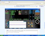
jetzt nach über ner stunde steht plötzlich GPS fix in der Kompassrose

aber nach wie vor keine Sat`s oder Positionsangabe

Zwischenablage01.jpg

ralf
 

bumerang

Erfahrener Benutzer
#7
Woran mag das liegen das keine sats angezeigt werden..das Daten kommen zeigt ja die blinkende Rose....zum heulen
und noch etwas ist mir aufgefallen...auf dem crius-Board blinkt ununterbrochen die gelbe Lampe (B). ziehe ich den stecker von Serial2 ab ist auch das blinken weg, sowohl am crius als auch in der kompassrose in der gui....
Ralf
 
Zuletzt bearbeitet:

quansel

Erfahrener Benutzer
#10
Welche Baudrate haste eingestellt?
Trotz aller Tips und Hinweise im Netz ... bei mir hat
NIX geklappt, bis ich die Baudrate auf 57600 gestellt habe ...

Teste mal!
Quansel
 

bumerang

Erfahrener Benutzer
#11
auch das hab ich schon probiert...
es blinkt einzig und allein die Kompassrose und die gelbe led auf dem crius
das ist die config.H die ich zur zeit drauf habe. kann sein das ich da evtl nen kompletten fehler drin habe....ist V 2.2

HTML:
  /**************************************************************************************/
  /***********************                  GPS                **************************/
  /**************************************************************************************/

    /* GPS using a SERIAL port
       if enabled, define here the Arduino Serial port number and the UART speed
       note: only the RX PIN is used in case of NMEA mode, the GPS is not configured by multiwii
       in NMEA mode the GPS must be configured to output GGA and RMC NMEA sentences (which is generally the default conf for most GPS devices)
       at least 5Hz update rate. uncomment the first line to select the GPS serial port of the arduino */
    #define GPS_SERIAL 2 // should be 2 for flyduino v2. It's the serial port number on arduino MEGA
    //#define GPS_BAUD   57600
    #define GPS_BAUD   115200


   /* GPS protocol 
       NMEA  - Standard NMEA protocol GGA, GSA and RMC  sentences are needed
       UBLOX - U-Blox binary protocol, use the ublox config file (u-blox-config.ublox.txt) from the source tree 
       MTK_BINARY16 and MTK_BINARY19 - MTK3329 chipset based GPS with DIYDrones binary firmware (v1.6 or v1.9)
       With UBLOX and MTK_BINARY you don't have to use GPS_FILTERING in multiwii code !!! */

    
    //#define NMEA
    #define UBLOX
    //#define MTK_BINARY16
    //#define MTK_BINARY19
    //#define INIT_MTK_GPS        // initialize MTK GPS for using selected speed, 5Hz update rate and GGA & RMC sentence or binary settings

    //#define GPS_PROMINI_SERIAL    57600 // Will Autosense if GPS is connected when ardu boots
   
    /* I2C GPS device made with an independant arduino + GPS device
       including some navigation functions
       contribution from EOSBandi   http://code.google.com/p/i2c-gps-nav/ 
       You have to use at least I2CGpsNav code r33 */
    //#define I2C_GPS

    /* I2C GPS device made with an indeedent ATTiny[24]313 + GPS device and
       optional sonar device.    https://github.com/wertarbyte/tiny-gps/ */
    /* get GPS data from Tiny-GPS */
    //#define TINY_GPS
    /* get sonar data from Tiny-GPS */
    //#define TINY_GPS_SONAR

    /* GPS data readed from Misio-OSD - GPS module connected to OSD, and MultiWii read GPS data from OSD - tested and working OK ! */
    //#define GPS_FROM_OSD

    /* indicate a valid GPS fix with at least 5 satellites by flashing the LED  - Modified by MIS - Using stable LED (YELLOW on CRIUS AIO) led work as sat number indicator 
      - No GPS FIX -> LED blink at speed of incoming GPS frames
      - Fix and sat no. bellow 5 -> LED off
      - Fix and sat no. >= 5 -> LED blinks, one blink for 5 sat, two blinks for 6 sat, three for 7 ... */
    #define GPS_LED_INDICATOR

    //#define USE_MSP_WP                        //Enables the MSP_WP command, which is used by WinGUI to display and log Home and Poshold positions

    //#define DONT_RESET_HOME_AT_ARM             // HOME position is reset at every arm, uncomment it to prohibit it (you can set home position with GyroCalibration)

    /* GPS navigation can control the heading */
    
    #define NAV_CONTROLS_HEADING       true      // copter faces toward the navigation point, maghold must be enabled for it
    #define NAV_TAIL_FIRST             true     // true - copter comes in with tail first 
    #define NAV_SET_TAKEOFF_HEADING    true      // true - when copter arrives to home position it rotates it's head to takeoff direction
    
    
    /* Get your magnetic decliniation from here : http://magnetic-declination.com/
       Convert the degree+minutes into decimal degree by ==> degree+minutes*(1/60)
       Note the sign on declination it could be negative or positive (WEST or EAST) */
    //#define MAG_DECLINIATION  3.96f              //For Budapest Hungary.
    #define MAG_DECLINIATION  1.26f

    #define GPS_LEAD_FILTER                      // Adds a forward predictive filterig to compensate gps lag. Code based on Jason Short's lead filter implementation
    
    //#define GPS_FILTERING                        // add a 5 element moving average filter to GPS coordinates, helps eliminate gps noise but adds latency comment out to disable
    #define GPS_WP_RADIUS              200       // if we are within this distance to a waypoint then we consider it reached (distance is in cm)
    #define NAV_SLEW_RATE              30        // Adds a rate control to nav output, will smoothen out nav angle spikes
 
Zuletzt bearbeitet:

bumerang

Erfahrener Benutzer
#16
Hab die Nase voll...Dat Ding geht morgen zurück zum Händler
Nach dem zweiten link bin ich vorgegangen bei der Installation.... Von I2C hab ich die Spannung geholt, vom seriell 2 TX und RX
Ralf
 
Zuletzt bearbeitet:

bumerang

Erfahrener Benutzer
#17
hallo.....nach fast schlafloser nacht und denken...mist...40 euronen für die Tonne

Fehler scheint gefunden, eher durch zufall aber ist ja eigentlich auch egal.....

das Modul war zu dicht an der FC, obwohl 2 Etagen dazwischen liegen, also gute 3cm mit 2 3mm dicken Paltten GFK...

wie kann ich es denn jetzt wirkungsvoll abschirmen damit es nicht mehr gestört wird?...habt ihr da ne idee für mich?

ralf
 

Ori0n

Back again
#18
Abstand
Die einzig wirkungsvolle Methode ist ausreichender Abstand.
ES gibt Leute, die benuten eine Mu-Metallfolie, die schrimt aberauch sämtliche Erdmagentfelder ab, daher keine gute Idee.
Am besten funktioniert ein großer Abstand, zumindest 5cm, mehr sind natürlich besser
 

Ori0n

Back again
#20
ja, stimmt.
ICh war mir nur nicht ganz sicher, ob er das MAG oder eh das GPS Modul gemeint hat, deshalb hab ichs sicherheitshalber mal dazugeschrieben, wenn es nur ums GPS geht, dann ist das Erdmagnetfeld natürlich komplett egal
 
FPV1

Banggood

Oben Unten