
Hallo All,
Sorry I do not speak much German, but I understand all of your English is fantastic here!
Recently I have got my hands a very unknown autopilot/OSD/Tracker all the way from Russia!
It PACKS so many features I thought I would share it here! This will be more of a review than anything, along with the set up procedure I will learn along the way and how it all fits!
Hopefully you have seen a teaser from my ‘Blog’ about this system, if not go check out the blogs here, full of great stuff!
So, let’s find out more!
The Sexy Box!
SwiftAi Mini OSD Basic Specifications
Processor is An Atmega8 16 MHz
Onboard Video separator LM1881
2 video amplifiers MAX4090 (video signal input from the camera, output to the video receiver)
Built-in 5V Regulator
Protection from reverse polarity when plugging in all sensors and power connector
PAL/NTSC Both Accepted
Nominal Voltage 6-15 V
Power consumption (with sensors and GPS module): <150mA
Dimensions 45х24х06 mm
Weight (without cables, sensors and GPS module): 6 g
Weight (with cables, sensors and GPS module): 49 g
Parameters viewable On The OSD
Flight time
Quality/Presence of RC signal receiving from the transmitter for PPM receivers
Height, according to barometric sensor: -999-9999 m (optional)
Aerial velocity: 0-350 km/hour (optional)
Temperature: -45 - +165°С
Current: 0-99А
Voltage (3 inputs): 0-15V, automatic detection of battery plugging
Expended battery charge: 0-9999 mA/h
Height according to GPS: -999-9999 m
Earth-related velocity according to GPS: 0-999 km/hour
Distance on the earth from the take-off point, according to GPS: 0..9999м
Current velocity vector direction: “compass” scale band
Direction to the take-off point: -180 - 180 degrees, “base” marked band
Variometer (height increase/decrease)
Amount of visible GPS satellites: 0-12
Position detection format for GPS module: NA / 2D / 3D
Latitude/Longitude in string format: 1234.567N/89012.345E
Adjustable parameters
Choice of velocity and height scales binding to baro sensors or GPS (at telemetric start)
Choice of telemetric screen – 3 screens and “output off” – during flight
Calibration
Auto calibration of velocity and height baro sensors at each start
Auto calibration of the current sensor at +5V voltage application to ADC7 input
Auto detection of video signal format (PAL/NTSC)
Auto detection of batteries plugging to the voltage inputs
Firmware Updatable
Images:
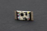
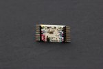
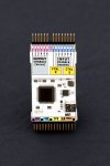
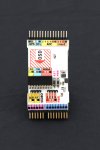
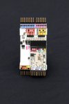
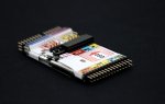
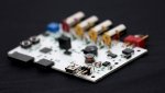
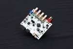
The Mini OSD can also piggy-back onto the autopilot board. Firmware updates for using with or without Autopilot board
This is what the MINI OSD looks like attached to the Autopilot module
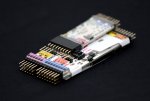
The Mini OSD has all the colour codes ready for you just to plug each sensor on the correct pins! Super simple stuff!
SwiftAi Autopilot Basic specifications
The Autopilot unit is based on the processor Atmel ATMega90 16 MHz with a USB port for connection to a PC or laptop and 2 MB of non-volatile memory to store calibration, Autopilot unit settings and logbook records.
Built-in stabilizers of +5В, +3.3V for power supply of the unit components
Protection against reverse polarity when all sensors and the power slot are connected
Nominal voltage: 6-15 V
Power consumption (including sensors) : <150mA
Size 77х39х11 mm
Size (when the telemetry board is connected): 77х39х11 mm
Weight: 36 g
Autopilot unit inputs and outputs
-6 input PPM channels for connection to the RC receiver
-6 output PPM channels for connection to the servos
-2 input PPM channels for operating mode control of the Autopilot unit
-MINI-USB connector for connection to PC
-SPI port for connection to the telemetry unit
-Video input and output connectors for the telemetry unit
-Connectors for the horizon sensors
Connectors for the daughter units and sensors:
-3 logic inputs-outputs
-3 analogue inputs
-I2C-bus for connection to up to 127 devices
-I2C-bus for connection to LRS receivers
-USART output
Autopilot unit features
Autopilot unit is connected between the RC receiver and the executive devices. Depending on the current mode, the unit either transmits PPM input signals unchanged or itself derives output signals for the servos.
Automatic orientation support of the model, according to the horizon sensors
Model control in the ‘fly by wire’ mode
Independent model control (return to the launching point) in the Autopilot mode
Model control in the Cruise control mode
Waypoint flights
Recording of flight parameters to the logbook with non-volatile memory
Data exchange with PC, during adjustment of the autopilot unit and reading of the logbook
Firmware update for the autopilot unit and telemetry
Control Panel features
Control Panel is a software unit for PC, designed to enable data exchange between the PC and the autopilot unit.
Multi-language interface
User-friendly arrangement of the components
Reading, modification and saving of the autopilot unit operating parameters
Reading from a file and saving of settings to a file
Reading from the memory and saving of settings to the autopilot unit memory
Firmware update for the autopilot unit and telemetry
Real time autopilot unit data monitoring when connected to USB:
The autopilot unit settings are made on PC using the Control Panel and are saved in the autopilot unit non-volatile memory.
Sensors and inputs parameters:
-Compass calibration
-Magnetic declination
RC channels calibration and parameters
-Channels ranges calibration
-Control commands calibration
-RC signal loss detection
-During PPM loss in channel
-During egress from calibrated range
Control channel calibration
5 positions
-Minimum
-Below average
-Average
-Above average
-Maximum
Choice of one of 5 commands for any position
No command
Telemetric screens switching
Autopilot and stabilizing forced switch-off
Stabilizing switch-on
Autopilot forced switch-on
Stabilizing system parameters:
Sensitivity for banking in all axis
Navigation system parameters:
Sensitivity for course
Sensitivity for height
Maximum allowed angles of banking and tangage
Maximum allowed backward turn velocity
GPS time-lag compensation
Target height (according to GPS or baro sensor)
Mode of obtaining target height
Target velocity (according to GPS or barosensor)
Minimum gas level (protection from stalling)
Forced gas level (protection from wind deflection)
Radius of gas forcing prohibition
Conditions of automatic Autopilot switch-on:
Loss of height on a distance
Height more than predetermined
Distance more than, value
-Voltage 1 less than, value
-Voltage 2 less than, value
-Voltage 3 less than, value
Battery discharge more than, value
Flight time more than, value
-RC signal loss
Conditions of Autopilot automatic switch-off:
Distance less than, value
Autopilot working time more than, value
RC signal return
Stabilized flight parameters
Tangage angle in outer positions of the stick
Banking angle in outer positions of the stick
Correction of horizon sensor position for tangage
Correction of horizon sensor position for banking
Log book parameters
Interval of data fixation in the log book
Gyroscopes control
Choice of gyroscope channel for banking
Choice of gyroscope channel for tangage
-PPM1 value in the output of gyroscope channel for banking
-PPM2 value in the output of gyroscope channel for banking
-PPM1 value in the output of gyroscope channel for tangage
-PPM2 value in the output of gyroscope channel for tangage
Telemetric module parameters
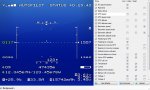
Depicting of parameters on the screen
Presence on screen, situation, font size, pictogram, presence of measurement units for the following parameters:
Quality/presence of RC signal
Flight time
Autopilot status bar
Velocity according to GPS
Velocity scale according to GPS
Height according to GPS
Height scale according to GPS
Velocity according to baro sensor
Velocity scale according to baro sensor
Height according to baro sensor
Height scale according to baro sensor
Course according to GPS
Course according to compass
Angle to starting point according to GPS
Angle to starting point according to compass
Artificial horizon
Distance from starting point
Amount of GPS satellites
GPS latitude/longitude
Temperature
Current
Battery discharge (value)
Battery discharge (indicator)
Voltage 1
Voltage 2
Voltage 3
Variometer according to GPS
Variometer according to baro sensor
Current sensor calibration
Battery monitoring parameters
Battery capacity
Used battery display
Warnings on the telemetric screen (blinking)
Height less than predetermined
Distance from start point more than, value
Voltage 1 less than, value
Voltage 2 less than, value
Voltage 3 less than, value
Battery consumption more than, value
Flight time more than, value
Images:
More images to follow...
Here is all of the sensors with images that are conectable to both Autopilot and Mini OSD
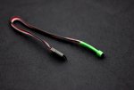
10Hz Gps Unit-
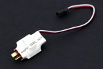
100amp Current Sensor-
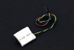
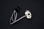
X-Y IR Sensors-
Z IR Sensor-
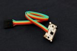
Static Speed Sensor (Top)
Static Bario (Bottom)
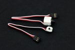
Temperature sensor-
The sensor supports -45 / +165 deg.C temperature range.
As you can see this hs a million things to it! It looks daunting but it should be easy to set up correctly!
SwiftAi Tracker
6-15v Nominal Power Supply
Inbuilt 5.5v (3amp) DC > DC Converter for 2 servos
High quality 1 to 3 video splitter based on Maxim Video Amps (powered by inbuilt linear regulator)
Audible Alarm
-Tracker board low voltage
-Lost / Damaged telementry data in the video signal
-Model Emergancy Situation
PC Set up Via MINI-USB port
Firmware upgrades (free)
I2C & UART (TTL) ports
Images:
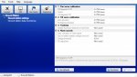
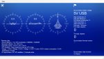
Pc Configuration Images
Start Up

AutoPilot Interface
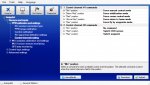


OSD Interface
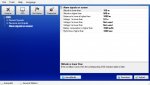

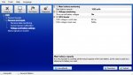
Tracking Interface
....Lots more to come on this!
Hope you are enjoying so far!
Ben
Sorry I do not speak much German, but I understand all of your English is fantastic here!
Recently I have got my hands a very unknown autopilot/OSD/Tracker all the way from Russia!
It PACKS so many features I thought I would share it here! This will be more of a review than anything, along with the set up procedure I will learn along the way and how it all fits!
Hopefully you have seen a teaser from my ‘Blog’ about this system, if not go check out the blogs here, full of great stuff!
So, let’s find out more!
The Sexy Box!
SwiftAi Mini OSD Basic Specifications
Processor is An Atmega8 16 MHz
Onboard Video separator LM1881
2 video amplifiers MAX4090 (video signal input from the camera, output to the video receiver)
Built-in 5V Regulator
Protection from reverse polarity when plugging in all sensors and power connector
PAL/NTSC Both Accepted
Nominal Voltage 6-15 V
Power consumption (with sensors and GPS module): <150mA
Dimensions 45х24х06 mm
Weight (without cables, sensors and GPS module): 6 g
Weight (with cables, sensors and GPS module): 49 g
Parameters viewable On The OSD
Flight time
Quality/Presence of RC signal receiving from the transmitter for PPM receivers
Height, according to barometric sensor: -999-9999 m (optional)
Aerial velocity: 0-350 km/hour (optional)
Temperature: -45 - +165°С
Current: 0-99А
Voltage (3 inputs): 0-15V, automatic detection of battery plugging
Expended battery charge: 0-9999 mA/h
Height according to GPS: -999-9999 m
Earth-related velocity according to GPS: 0-999 km/hour
Distance on the earth from the take-off point, according to GPS: 0..9999м
Current velocity vector direction: “compass” scale band
Direction to the take-off point: -180 - 180 degrees, “base” marked band
Variometer (height increase/decrease)
Amount of visible GPS satellites: 0-12
Position detection format for GPS module: NA / 2D / 3D
Latitude/Longitude in string format: 1234.567N/89012.345E
Adjustable parameters
Choice of velocity and height scales binding to baro sensors or GPS (at telemetric start)
Choice of telemetric screen – 3 screens and “output off” – during flight
Calibration
Auto calibration of velocity and height baro sensors at each start
Auto calibration of the current sensor at +5V voltage application to ADC7 input
Auto detection of video signal format (PAL/NTSC)
Auto detection of batteries plugging to the voltage inputs
Firmware Updatable
Images:
The Mini OSD can also piggy-back onto the autopilot board. Firmware updates for using with or without Autopilot board
This is what the MINI OSD looks like attached to the Autopilot module
The Mini OSD has all the colour codes ready for you just to plug each sensor on the correct pins! Super simple stuff!
SwiftAi Autopilot Basic specifications
The Autopilot unit is based on the processor Atmel ATMega90 16 MHz with a USB port for connection to a PC or laptop and 2 MB of non-volatile memory to store calibration, Autopilot unit settings and logbook records.
Built-in stabilizers of +5В, +3.3V for power supply of the unit components
Protection against reverse polarity when all sensors and the power slot are connected
Nominal voltage: 6-15 V
Power consumption (including sensors) : <150mA
Size 77х39х11 mm
Size (when the telemetry board is connected): 77х39х11 mm
Weight: 36 g
Autopilot unit inputs and outputs
-6 input PPM channels for connection to the RC receiver
-6 output PPM channels for connection to the servos
-2 input PPM channels for operating mode control of the Autopilot unit
-MINI-USB connector for connection to PC
-SPI port for connection to the telemetry unit
-Video input and output connectors for the telemetry unit
-Connectors for the horizon sensors
Connectors for the daughter units and sensors:
-3 logic inputs-outputs
-3 analogue inputs
-I2C-bus for connection to up to 127 devices
-I2C-bus for connection to LRS receivers
-USART output
Autopilot unit features
Autopilot unit is connected between the RC receiver and the executive devices. Depending on the current mode, the unit either transmits PPM input signals unchanged or itself derives output signals for the servos.
Automatic orientation support of the model, according to the horizon sensors
Model control in the ‘fly by wire’ mode
Independent model control (return to the launching point) in the Autopilot mode
Model control in the Cruise control mode
Waypoint flights
Recording of flight parameters to the logbook with non-volatile memory
Data exchange with PC, during adjustment of the autopilot unit and reading of the logbook
Firmware update for the autopilot unit and telemetry
Control Panel features
Control Panel is a software unit for PC, designed to enable data exchange between the PC and the autopilot unit.
Multi-language interface
User-friendly arrangement of the components
Reading, modification and saving of the autopilot unit operating parameters
Reading from a file and saving of settings to a file
Reading from the memory and saving of settings to the autopilot unit memory
Firmware update for the autopilot unit and telemetry
Real time autopilot unit data monitoring when connected to USB:
The autopilot unit settings are made on PC using the Control Panel and are saved in the autopilot unit non-volatile memory.
Sensors and inputs parameters:
-Compass calibration
-Magnetic declination
RC channels calibration and parameters
-Channels ranges calibration
-Control commands calibration
-RC signal loss detection
-During PPM loss in channel
-During egress from calibrated range
Control channel calibration
5 positions
-Minimum
-Below average
-Average
-Above average
-Maximum
Choice of one of 5 commands for any position
No command
Telemetric screens switching
Autopilot and stabilizing forced switch-off
Stabilizing switch-on
Autopilot forced switch-on
Stabilizing system parameters:
Sensitivity for banking in all axis
Navigation system parameters:
Sensitivity for course
Sensitivity for height
Maximum allowed angles of banking and tangage
Maximum allowed backward turn velocity
GPS time-lag compensation
Target height (according to GPS or baro sensor)
Mode of obtaining target height
Target velocity (according to GPS or barosensor)
Minimum gas level (protection from stalling)
Forced gas level (protection from wind deflection)
Radius of gas forcing prohibition
Conditions of automatic Autopilot switch-on:
Loss of height on a distance
Height more than predetermined
Distance more than, value
-Voltage 1 less than, value
-Voltage 2 less than, value
-Voltage 3 less than, value
Battery discharge more than, value
Flight time more than, value
-RC signal loss
Conditions of Autopilot automatic switch-off:
Distance less than, value
Autopilot working time more than, value
RC signal return
Stabilized flight parameters
Tangage angle in outer positions of the stick
Banking angle in outer positions of the stick
Correction of horizon sensor position for tangage
Correction of horizon sensor position for banking
Log book parameters
Interval of data fixation in the log book
Gyroscopes control
Choice of gyroscope channel for banking
Choice of gyroscope channel for tangage
-PPM1 value in the output of gyroscope channel for banking
-PPM2 value in the output of gyroscope channel for banking
-PPM1 value in the output of gyroscope channel for tangage
-PPM2 value in the output of gyroscope channel for tangage
Telemetric module parameters
Depicting of parameters on the screen
Presence on screen, situation, font size, pictogram, presence of measurement units for the following parameters:
Quality/presence of RC signal
Flight time
Autopilot status bar
Velocity according to GPS
Velocity scale according to GPS
Height according to GPS
Height scale according to GPS
Velocity according to baro sensor
Velocity scale according to baro sensor
Height according to baro sensor
Height scale according to baro sensor
Course according to GPS
Course according to compass
Angle to starting point according to GPS
Angle to starting point according to compass
Artificial horizon
Distance from starting point
Amount of GPS satellites
GPS latitude/longitude
Temperature
Current
Battery discharge (value)
Battery discharge (indicator)
Voltage 1
Voltage 2
Voltage 3
Variometer according to GPS
Variometer according to baro sensor
Current sensor calibration
Battery monitoring parameters
Battery capacity
Used battery display
Warnings on the telemetric screen (blinking)
Height less than predetermined
Distance from start point more than, value
Voltage 1 less than, value
Voltage 2 less than, value
Voltage 3 less than, value
Battery consumption more than, value
Flight time more than, value
Images:
More images to follow...
Here is all of the sensors with images that are conectable to both Autopilot and Mini OSD
10Hz Gps Unit-
100amp Current Sensor-
X-Y IR Sensors-
Z IR Sensor-
Static Speed Sensor (Top)
Static Bario (Bottom)
Temperature sensor-
The sensor supports -45 / +165 deg.C temperature range.
As you can see this hs a million things to it! It looks daunting but it should be easy to set up correctly!
SwiftAi Tracker
6-15v Nominal Power Supply
Inbuilt 5.5v (3amp) DC > DC Converter for 2 servos
High quality 1 to 3 video splitter based on Maxim Video Amps (powered by inbuilt linear regulator)
Audible Alarm
-Tracker board low voltage
-Lost / Damaged telementry data in the video signal
-Model Emergancy Situation
PC Set up Via MINI-USB port
Firmware upgrades (free)
I2C & UART (TTL) ports
Images:
Pc Configuration Images
Start Up
AutoPilot Interface
OSD Interface
Tracking Interface
....Lots more to come on this!
Hope you are enjoying so far!
Ben
") Whre can I buy it and what does it cost??
Whre can I buy it and what does it cost??