
Open Source Brushless Gimbal Controller
- Themenstarter RC FAN2
- Beginndatum
- Status
- Nicht offen für weitere Antworten.
![IMG_2008[1].jpg](/data/attachments/30/30791-e25c7865dcdff192f710d79aab82b4c9.jpg)
Hallo Harald
Also Mit Senkrecht meine ich die Grunposition der Kamera also Linse nach vorn. 10° Abweichung um diesen Punkt ist Quasi wenn ich den Copter um 10° in nick vor und zurückneige. sobald die Neigung höher wird läuft alles gut. (bis dann der Moment 90° kommt und die Regelung aussteigt) Ich habe dieses MPU
http://www.ebay.de/itm/121078332904?ssPageName=STRK:MEWNX:IT&_trksid=p3984.m1497.l2649
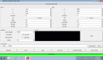
Meine momentanen Einstellungen hänge ich mal als Bild an.
Accel Weight kann ich runter stellen bis 0.0001 dann wird das Erreichen der Grundstellung sehr lahm aber das Summen bleibt.
Bei P unter 10 wird eierig.
Gruß Sven
Also Mit Senkrecht meine ich die Grunposition der Kamera also Linse nach vorn. 10° Abweichung um diesen Punkt ist Quasi wenn ich den Copter um 10° in nick vor und zurückneige. sobald die Neigung höher wird läuft alles gut. (bis dann der Moment 90° kommt und die Regelung aussteigt) Ich habe dieses MPU
http://www.ebay.de/itm/121078332904?ssPageName=STRK:MEWNX:IT&_trksid=p3984.m1497.l2649
Meine momentanen Einstellungen hänge ich mal als Bild an.
Accel Weight kann ich runter stellen bis 0.0001 dann wird das Erreichen der Grundstellung sehr lahm aber das Summen bleibt.
Bei P unter 10 wird eierig.
Gruß Sven
Anhänge
-
 118,6 KB Aufrufe: 112
Hab mal nem Frage zum Brugi AIO Board. Hat die Stromversorgung eine Sicherung? Wenn ich das Board per USB anschließe geht alles, wenn ich den Hauptstromanschluss benutze geht garnix. Also die Motoren sprechen auch an beim USB, nur eben sehr langsam und ohne Kraft. Verpolt ist auch nix. Akkus ist ein 4S. Bin ein wenig ratlos und hoffe ihr könnt helfen.
Gruß Roman
Edit: Glaube habs gefunden, habe mir den Schaltplan mal angesehn und den Widerstand R3 überbrückt. Board bekommt jetzt wieder Strom. Ist R3 nur eine Sicherung oder ist das wirklich ein Widerstand? Weil kein Ohmwert dran steht.
Gruß Roman
Edit: Glaube habs gefunden, habe mir den Schaltplan mal angesehn und den Widerstand R3 überbrückt. Board bekommt jetzt wieder Strom. Ist R3 nur eine Sicherung oder ist das wirklich ein Widerstand? Weil kein Ohmwert dran steht.
Zuletzt bearbeitet:
Hallo Leute,
Ich hab mir eine Brushless Gimbal Control von RC-Timer gekauft. Scheitere aber daran mit der GUI zu verbinden. Jetzt hab ich das Tutorial einige Seiten vorher von The Highlander verfolgt, weis aber nicht welches Board ich auswählen muss. Weis jemand wie man das herausfindet?
MFG
Fungames
Ich hab mir eine Brushless Gimbal Control von RC-Timer gekauft. Scheitere aber daran mit der GUI zu verbinden. Jetzt hab ich das Tutorial einige Seiten vorher von The Highlander verfolgt, weis aber nicht welches Board ich auswählen muss. Weis jemand wie man das herausfindet?
MFG
Fungames
gug dir mal das Video an
Sollten alle deine Fragen beantworten
http://www.youtube.com/watch?feature=player_embedded&v=T2BXGY4g9kA
Sollten alle deine Fragen beantworten
http://www.youtube.com/watch?feature=player_embedded&v=T2BXGY4g9kA
Hallo, zuerst hier posten und ich bin mit Google Translate so entschuldigt bitte die Rechtschreibung oder Bedeutung. Ich hoffe, dies ist der richtige Thread, gibt es mehrere gleichzeitig aktiv sind. ") Ich entschuldige mich für den Spruch für jeden offensichtlich über P, I, D, max PWM, aber wir haben keine klaren Angaben zum Englisch RCGroups.
Ich entschuldige mich für den Spruch für jeden offensichtlich über P, I, D, max PWM, aber wir haben keine klaren Angaben zum Englisch RCGroups.
Nach der Feststellung, niemanden, der jemals die perfekten Einstellungen für ihre Gimbal und da es keine Anweisungen für die Einstellung der neuen 048 PID Werte, die ich getestet, um zu sehen, wie sie miteinander in Beziehung gefunden hat.
Ich fand für einen einzelnen Wert von P, dann ist die maxPWM macht die Aufhängung tatsächlich bewegen. Zu klein Macht und Gimbal Kämpfe Niveau bleiben (Sie kennen diese). Ich war darauf bedacht, einen guten Wert, ohne zu viel Wärme in den Motoren haben. Sobald der Gimbal ist glücklich, gut stabilisieren, halte ich die Erhöhung der max PWM als Genauigkeit nicht verbessert, nur Wärme. Für mein Licht Gimbal max PWM = 65 ist ein guter Wert.
Ich experimentierte mit dem P und festgestellt, dass es erhöht die Genauigkeit erhöht. Ich habe diesen Test mit Iacc = 0, so gab es keine "Korrektur" der falschen Winkel.
Mein Test wurde bei 0 Grad halten Gimbal, starten Sie den Chart, drehen Sie die Gimbal 90 Grad und lesen Sie die Rolle auf dem Chart. Der Unterschied ist, Fehler bei der Umwandlung des Roll Motor richtig. Mit P = 20 Grad der Fehler = 13 und P = 60 Grad der Störung ist 4. Ich müsste P = 100 Grad für Fehler = 0 ist. Nicht möglich, da mit zunehmender P muss auch in PWM max verringern, aber Gimbalisch ist zu schwach.
Halten in gleichen 90-Grad-Position Gimbal und Einstellung Iacc> 0 und die Aufhängung wird Ebene mit der Geschwindigkeit proportional zur Iacc.
Also, es ist eine sehr einfache Aufgabe, um die richtige max PWM eingestellt und dann den höchsten P für höchste Genauigkeit und mit D Vibrationen zu steuern, um den bestmöglichen Wert für ein bestimmtes Gimbal / Motoren zu bekommen. Ich fand, dass die Festlegung Iacc auf eine große Anzahl (10 +), um den Fehler schnell zu korrigieren, ist nicht gut, da dann die Gimbal-Acts wie max PWM ist niedrig und die Halteposition ist schwach. Der Kompromiss besteht darin, Iacc auf 1,0 gesetzt und haben die Fehlerkorrektur langsam sein, aber der Gimbal hält stabil.
Meine kleinste Fehler bei 90 Grad = 4 Grad = 4,4% Fehler. Ich habe in den Code zu versuchen und finden einen guten Platz, um den Motor zu sagen, von 104,4% drehen (oder 95,6%, wenn umgekehrter gesetzt) gesucht, aber habe es nicht gefunden. Es scheint, als sollte dies ein einfacher Wert, um den Befehl zu überschreiben, um die Motoren drehen sein, und es könnte ein Feld sein in der GUI, um einen Wert für jeden Motor, nachdem wir den Fehler für unsere besondere Gimbal und P, I, D, max bestimmen PWM Einstellungen wir sind am glücklichsten mit.
Ist das ein korrektes Verständnis des Problems und wo kann diese zusätzliche Berechnung im Code vorgenommen werden?
Wenn es nicht möglich dies zu tun, müssen Sie die Kommentare anderer Änderungen, die wir machen? Verschiedene Motorwicklungen, Ohm, Batterie, andere?
Beigefügt ist Graphen meiner Grad der Fehler Befund und Links zu meinen Beiträgen in RCGroups. link, link, link, link


Ich entschuldige mich für den Spruch für jeden offensichtlich über P, I, D, max PWM, aber wir haben keine klaren Angaben zum Englisch RCGroups.Nach der Feststellung, niemanden, der jemals die perfekten Einstellungen für ihre Gimbal und da es keine Anweisungen für die Einstellung der neuen 048 PID Werte, die ich getestet, um zu sehen, wie sie miteinander in Beziehung gefunden hat.
Ich fand für einen einzelnen Wert von P, dann ist die maxPWM macht die Aufhängung tatsächlich bewegen. Zu klein Macht und Gimbal Kämpfe Niveau bleiben (Sie kennen diese
). Ich war darauf bedacht, einen guten Wert, ohne zu viel Wärme in den Motoren haben. Sobald der Gimbal ist glücklich, gut stabilisieren, halte ich die Erhöhung der max PWM als Genauigkeit nicht verbessert, nur Wärme. Für mein Licht Gimbal max PWM = 65 ist ein guter Wert.Ich experimentierte mit dem P und festgestellt, dass es erhöht die Genauigkeit erhöht. Ich habe diesen Test mit Iacc = 0, so gab es keine "Korrektur" der falschen Winkel.
Mein Test wurde bei 0 Grad halten Gimbal, starten Sie den Chart, drehen Sie die Gimbal 90 Grad und lesen Sie die Rolle auf dem Chart. Der Unterschied ist, Fehler bei der Umwandlung des Roll Motor richtig. Mit P = 20 Grad der Fehler = 13 und P = 60 Grad der Störung ist 4. Ich müsste P = 100 Grad für Fehler = 0 ist. Nicht möglich, da mit zunehmender P muss auch in PWM max verringern, aber Gimbalisch ist zu schwach.
Halten in gleichen 90-Grad-Position Gimbal und Einstellung Iacc> 0 und die Aufhängung wird Ebene mit der Geschwindigkeit proportional zur Iacc.
Also, es ist eine sehr einfache Aufgabe, um die richtige max PWM eingestellt und dann den höchsten P für höchste Genauigkeit und mit D Vibrationen zu steuern, um den bestmöglichen Wert für ein bestimmtes Gimbal / Motoren zu bekommen. Ich fand, dass die Festlegung Iacc auf eine große Anzahl (10 +), um den Fehler schnell zu korrigieren, ist nicht gut, da dann die Gimbal-Acts wie max PWM ist niedrig und die Halteposition ist schwach. Der Kompromiss besteht darin, Iacc auf 1,0 gesetzt und haben die Fehlerkorrektur langsam sein, aber der Gimbal hält stabil.
Meine kleinste Fehler bei 90 Grad = 4 Grad = 4,4% Fehler. Ich habe in den Code zu versuchen und finden einen guten Platz, um den Motor zu sagen, von 104,4% drehen (oder 95,6%, wenn umgekehrter gesetzt) gesucht, aber habe es nicht gefunden. Es scheint, als sollte dies ein einfacher Wert, um den Befehl zu überschreiben, um die Motoren drehen sein, und es könnte ein Feld sein in der GUI, um einen Wert für jeden Motor, nachdem wir den Fehler für unsere besondere Gimbal und P, I, D, max bestimmen PWM Einstellungen wir sind am glücklichsten mit.
Ist das ein korrektes Verständnis des Problems und wo kann diese zusätzliche Berechnung im Code vorgenommen werden?
Wenn es nicht möglich dies zu tun, müssen Sie die Kommentare anderer Änderungen, die wir machen? Verschiedene Motorwicklungen, Ohm, Batterie, andere?
Beigefügt ist Graphen meiner Grad der Fehler Befund und Links zu meinen Beiträgen in RCGroups. link, link, link, link
Hi Brandigan ,
You can also post in english
You can also post in english
Hopefully Google Translate didn't garble what I asked too much. I did put the translation back through E>G>E>G it a few times to try and check it was retaining most of the meaning.
My query is: how possible is it to have an override on the calculation used by the software to rotate each motor to the correct position, once we find out how big we want that override to be by finding out what our gimbal's particular margin of error is? I assume it is different for every motor/gimbal/setup. The fact accuracy changes with both P and max PWM is what has us all chasing our tails.
The software seems to get the correct angle information from the MPU, but then fails to turn the motors quite far enough when IAcc=0. If IAcc>0 it corrects, so it does 'know' it is wrong, but it seems like an imperfect solution.
Can we say to the firmware: "OK, that's close, but not quite right, and I have worked out the 'error %' by doing a calibration, please use this multiplier of nn% on the value you though you needed to correctly rotate the motor"?
Or, is it simple a loss of precision over several calculations that produces a larger error as the angle increases?
Or is there anything else we should be doing? Because it seems there is really only one optimum way to set up each gimbal: Enough power to hold gimbal+Highest P allowed for that power+enough D to stop vibrations( + small IAcc to correct error).
Once that is done, we have optimised the settings for our particular hardware, so does the hardware need to change?
Hey Brandigan,
I have seen your posts at rcg but must admit I couldn't make much sense of them, but your last post condensed them nicely.
in principle one could correct a small missalignment as you suggest, BUT the correction which you need to apply might be different any time - not very convennient. However, it can be done in a smarter way, namely to build in a mechanism which measures the missalignment permanently and corrects for it as soon as it detects one... and this is exactly the mechanism which you enable by IAcc > 0!
The buzz word here is PID controller; you may wish to read the wikipedia and/or rn wiki pages. Should be very helpfull to better understand the concept of PID controllers and meaning of P, I, D.
You will in fact discover there that, then I = 0, the difference between the target angle and the actual angle will become smaller and smaller with increasing P, which is exactly what you observe in your plots! (this is actually one of the most basic properties which one is getting told in an PID introduction)
no, it's totally unrelated to precisson, its a basic fact of PID controllers
With version 048 the IAcc was made to have TWO functions simultaneously, namely to act as I in the PID controller (which is what we were talking about few lines before), and to control the fusing of the data from the gyro and accelerometer. Personally I find this a bit unfortunate, since a potentially usefull tuning capability is given away without any need, and I am kind of willing to bet that separating these two features will be (re)implemented in a future version. For the moment, you got the tuning recipe quite right.
you should be aware that by principle the parameters have to be tuned to work best for a particular hardware (or very similar hardware). Whenever the hardware changes significantly, you have to retune. I repeat, this is by principle, and there is little you can do about (except of implementing so called autotuners, which however can have their very own issues)
I have seen your posts at rcg but must admit I couldn't make much sense of them, but your last post condensed them nicely.
The software seems to get the correct angle information from the MPU, but then fails to turn the motors quite far enough when IAcc=0. If IAcc>0 it corrects, so it does 'know' it is wrong, but it seems like an imperfect solution.
Can we say to the firmware: "OK, that's close, but not quite right, and I have worked out the 'error %' by doing a calibration, please use this multiplier of nn% on the value you though you needed to correctly rotate the motor"?
Can we say to the firmware: "OK, that's close, but not quite right, and I have worked out the 'error %' by doing a calibration, please use this multiplier of nn% on the value you though you needed to correctly rotate the motor"?
The buzz word here is PID controller; you may wish to read the wikipedia and/or rn wiki pages. Should be very helpfull to better understand the concept of PID controllers and meaning of P, I, D.
You will in fact discover there that, then I = 0, the difference between the target angle and the actual angle will become smaller and smaller with increasing P, which is exactly what you observe in your plots! (this is actually one of the most basic properties which one is getting told in an PID introduction)
Or, is it simple a loss of precision over several calculations that produces a larger error as the angle increases?
Or is there anything else we should be doing? Because it seems there is really only one optimum way to set up each gimbal: Enough power to hold gimbal+Highest P allowed for that power+enough D to stop vibrations( + small IAcc to correct error). Once that is done, we have optimised the settings for our particular hardware, so does the hardware need to change?
Once that is done, we have optimised the settings for our particular hardware, so does the hardware need to change?
I will read up on PID controllers to understand more.
I understand that the values will be different for different hardware, but with Acc=0 for a particular gimbal, PID and power values, the error margin seemed constant for me. I didn't seem to vary with voltage, as the battery I was using went from 12.6v to 11.2v over several hours and there was no noticeable change in the error value.
You say setting a value in IAcc is the smarter way, but it is either slow to adjust, or if there is a too high IAcc value it makes the gimbal go weak, as it seems to cancel out P and max PWM to some extent. It is that weakness that makes using high IAcc not very effective in 'hiding' the error. Is that an unavoidable side-effect?
Are you also saying it is not possible to ever set the angle correctly with IAcc=0, even though it is possible to tell that the gimbal is not level?
It doesn't seem like a hardware problem, only software, because depending on the setting of the reverse flag, it is possible to make the gimbal turn by too small an angle and also too large. So I'm not sure I understand why it is not possible to have it be inbetween those two incorrect points and be at the correct angle.
IMHO there is no way out, you need to understand first the basics of PID... otherwise you can fill pages of text running from one riddle to the next...
let me attempt a simple yet general explanation
you are the controller now and have to set the gimbal level... so I tell you now, please set the gimbal level... BUT... you are not allowed to open your eyes! ... ... ... I guess you will not succeed, although I can clearly see that the gimbal is not level, and I will ask you hence, hey, why haven't you set it level even though I can tell that it is not level?
it's not a perfekt analogy and shouldn't be overstressed, but if you set I = 0 it's kind of me telling you to keep your eyes shut...
The bottomline: if one takes away some function then one shouldn't be surprised that the task the functions was for isn't accomplished.
Are you also saying it is not possible to ever set the angle correctly with IAcc=0, even though it is possible to tell that the gimbal is not level?
you are the controller now and have to set the gimbal level... so I tell you now, please set the gimbal level... BUT... you are not allowed to open your eyes! ... ... ... I guess you will not succeed, although I can clearly see that the gimbal is not level, and I will ask you hence, hey, why haven't you set it level even though I can tell that it is not level?
it's not a perfekt analogy and shouldn't be overstressed, but if you set I = 0 it's kind of me telling you to keep your eyes shut...
The bottomline: if one takes away some function then one shouldn't be surprised that the task the functions was for isn't accomplished.
in principle one could correct a small missalignment as you suggest, BUT the correction which you need to apply might be different any time - not very convennient.
I'm not sure why it would be different at any time once you have calculated it and do not change anything on your gimbal. The error has been consistent for me, so I would hope the correction would as well.
I personally did not find it varied with voltage (1000aAh 3s AR.Drone battery) but if it might do with larger or different motors (or other setups), then the solution would be to have a large enough battery and be aware that it would be less accurate over time, but if you are starting with a zero degree error, I could certainly put up with that rather than starting with a 13 <> 4 degree error.
So, if it's possible, how can it be done? Even if it's not perfect or the final option, any improvement is better than none.
let me attempt a simple yet general explanation
you are the controller now and have to set the gimbal level... so I tell you now, please set the gimbal level... BUT... you are not allowed to open your eyes! ... ... ... I guess you will not succeed, although I can clearly see that the gimbal is not level, and I will ask you hence, hey, why haven't you set it level even though I can tell that it is not level?
it's not a perfekt analogy and shouldn't be overstressed, but if you set I = 0 it's kind of me telling you to keep your eyes shut...
The bottomline: if one takes away some function then one shouldn't be surprised that the task the functions was for isn't accomplished.
but if I say "Well, I turned by this much and I thought it was level, which is why I stopped, based on the other tactile information I had from not using my eyes" and you say "No, turn by 5% more for what you think is level" and I do that with my eyes shut (I have feeling, otherwise I couldn't turn it at all). then....it's level.The way IAcc is working just seems slightly faulty. Setting a high value that not only levels the gimbal, but also removes the power so it moves in a breeze isn't so useful. if it did one without the other, then...fine.
At the moment, I'm not sure that IAcc is being used to get the best results, it's a little like a bandaid.
Zuletzt bearbeitet:
Well, I've read a little about PIDs in the wiki and I think I'll go back to 046, which seems to be a purer interpretation of the system - rather than combining I and Acc together as in 048 - and have a hack about with the code some more.
There is unfortunately the bug in 046 that with a value of 0 in 'ACC' it has an effect depending on whether you select "Use Acc" or not. Which was why I asked if there could be a precision error somewhere, as using or not using 0 shouldn't really make a difference.
There is unfortunately the bug in 046 that with a value of 0 in 'ACC' it has an effect depending on whether you select "Use Acc" or not. Which was why I asked if there could be a precision error somewhere, as using or not using 0 shouldn't really make a difference.
- Status
- Nicht offen für weitere Antworten.