
Baubericht X525 Quadrokopter mir MultiWii SE 2.1 und GPS über I2C
- Themenstarter Q-Man
- Beginndatum
Ich habe auch die Spinner, die bei der Lieferung von GoodLuckBuy dabei waren. Aufstecken und der Schraube über dem Propeller wird die Halterung angepresst. Mir ist auch noch nie eine Fliegen gegangen.
reimundko: Schau mal bei Ebay nach "Spinner Propeller", wichtig ist der richtige Wellendurchmesser des Motors.
Hier einfach mal ein Bild von Motor und Spinner:

reimundko: Schau mal bei Ebay nach "Spinner Propeller", wichtig ist der richtige Wellendurchmesser des Motors.
Hier einfach mal ein Bild von Motor und Spinner:
Zuletzt bearbeitet:
So nun bin ich ein wenig weiter gekommen.
Die Motoren lassen sich endlich starten.
Musste den MINTHROTTLE etwas niedriger stellen und bei der Funke auch ändern.
Nun laufen die Motoren an.
Allerdings habe ich noch 2 Probleme.
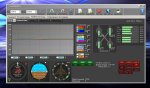
Beim scharf stellen des Boards laufen nur 2 Motoren. Bei Mittelgas gehen alle Motoren an.
Siehe Bild.
Wie kann ich das nun ändern, dass alle gleich laufen ?
2. Problem. Wenn ich den Gashebel nach unten bewege gehen alle Motoren aus. Glaube das ist doch nicht so gewollt oder, Kann man das auch beheben.
Danke
Die Motoren lassen sich endlich starten.
Musste den MINTHROTTLE etwas niedriger stellen und bei der Funke auch ändern.
Nun laufen die Motoren an.
Allerdings habe ich noch 2 Probleme.
Beim scharf stellen des Boards laufen nur 2 Motoren. Bei Mittelgas gehen alle Motoren an.
Siehe Bild.
Wie kann ich das nun ändern, dass alle gleich laufen ?
2. Problem. Wenn ich den Gashebel nach unten bewege gehen alle Motoren aus. Glaube das ist doch nicht so gewollt oder, Kann man das auch beheben.
Danke
Anhänge
-
 109,9 KB Aufrufe: 28
Ich denke mal du hast Minthrottle zu tief stehen. Ich habe 1150 als Leerlauf Drehzahl eingestellt.
Wenn ich mir aber ansehe, das deine Motoren bei über 1400 noch nicht laufen, würde ich tippen, das du die Motorregler nicht configuriert hast.
Ich habe das so gemacht. In der Config.h: #define ESC_CALIB_CANNOT_FLY // uncomment to activate
nicht mehr auskommentieren und Werte setzen:
#define ESC_CALIB_LOW MINCOMMAND
#define ESC_CALIB_HIGH 2000
/**************************** Mincommand *******************************/
/* this is the value for the ESCs when they are not armed
in some cases, this value must be lowered down to 900 for some specific ESCs, otherwise they failed to initiate */
#define MINCOMMAND 1000
Diese Output: ist speziell für meine ESCs gedacht.
/******** special version of MultiWii to calibrate all attached ESCs ************/
#if defined(ESC_CALIB_CANNOT_FLY)
writeAllMotors(ESC_CALIB_HIGH);
delay(11000);
writeAllMotors(ESC_CALIB_LOW);
delay(1000);
writeAllMotors(ESC_CALIB_HIGH);
delay(500);
writeAllMotors(ESC_CALIB_LOW);
delay(500);
while (1) { //ENDLOSSCHLEIFE
delay(500);
blinkLED(2,20, 2);
}
exit; // statement never reached
#endif
Ich hoffe das dir das Helfen wird.
Danke werde es mal probieren.
Ich habe die 20 A von Hobbywing
So habe den Wert nun auf 2000 hoch gesetzt.
Wenn ich nun das Board scharf stelle laufen ALLe Motoren an. Danke für die Hilfeleistung.
Allerdings wenn ich den Gashebel runter mache und links schalten sich die Motoren nicht ab.
So werde nun den Mittelwert noch einstellen und dann nochmals die ECS anlernen.
Glaube mein Fehler war dass ich die zuerst angelernt habe, dann das Board eingestellt habe, musste ja auch die Fernsteuerung ja höher setzen damit ich auf maximal 2000 kam.
Habe also zu früh die Gas angelernt.
Zuletzt bearbeitet:
Danke also habe alles in der Mitte bekommen.
Danach habe ich nochmals die Regler alle EINZELN angelernt.
Also Sender ein. Gas nach oben, Empfänger an, Motor piepst, danach nach unten den Gas Regler, wieder das Piepsen. Fertig.
Lässt sich nun regeln.
Das mit den anderen 3 auch gemacht.
Alles wieder angeschlossen.
Nun kommen die 2 Probleme.
Die Motoren laufen immer noch nicht alle gleich.
Und ich bekomme die Motoren nicht mehr ausgeschaltet.
Es sollte doch Gas Runter und dann nach links ausgeschaltet werden.
Funktioniert leider nicht.
Hier mal die Config.
/*************************************************************************************************/
/***************** ***************/
/**************** SECTION 1 - BASIC SETUP *******/
/***************** ***************/
/*************************************************************************************************/
/************************** The type of multicopter ****************************/
//#define GIMBAL
//#define BI
//#define TRI
//#define QUADP
#define QUADX
//#define Y4
//#define Y6
//#define HEX6
//#define HEX6X
//#define OCTOX8
//#define OCTOFLATP
//#define OCTOFLATX
//#define FLYING_WING
//#define VTAIL4
//#define AIRPLANE
//#define SINGLECOPTER
//#define DUALCOPTER
//#define HELI_120_CCPM
//#define HELI_90_DEG
/**************************** Motor minthrottle *******************************/
/* Set the minimum throttle command sent to the ESC (Electronic Speed Controller)
This is the minimum value that allow motors to run at a idle speed */
//#define MINTHROTTLE 1300 // for Turnigy Plush ESCs 10A
//#define MINTHROTTLE 1120 // for Super Simple ESCs 10A
//#define MINTHROTTLE 1064 // special ESC (simonk)
#define MINTHROTTLE 1300
/**************************** Motor maxthrottle *******************************/
/* this is the maximum value for the ESCs at full power, this value can be increased up to 2000 */
#define MAXTHROTTLE 2000
/**************************** Mincommand *******************************/
/* this is the value for the ESCs when they are not armed
in some cases, this value must be lowered down to 900 for some specific ESCs, otherwise they failed to initiate */
#define MINCOMMAND 1000
/********************************** I2C speed ************************************/
#define I2C_SPEED 100000L //100kHz normal mode, this value must be used for a genuine WMP
//#define I2C_SPEED 400000L //400kHz fast mode, it works only with some WMP clones
/*************************** Internal i2c Pullups ********************************/
/* enable internal I2C pull ups (in most cases it is better to use external pullups) */
//#define INTERNAL_I2C_PULLUPS
/**************************************************************************************/
/***************** boards and sensor definitions ******************/
/**************************************************************************************/
/*************************** Combined IMU Boards ********************************/
/* if you use a specific sensor board:
please submit any correction to this list.
Note from Alex: I only own some boards, for other boards, I'm not sure, the info was gathered via rc forums, be cautious */
//#define FFIMUv1 // first 9DOF+baro board from Jussi, with HMC5843 <- confirmed by Alex
//#define FFIMUv2 // second version of 9DOF+baro board from Jussi, with HMC5883 <- confirmed by Alex
//#define FREEIMUv1 // v0.1 & v0.2 & v0.3 version of 9DOF board from Fabio
//#define FREEIMUv03 // FreeIMU v0.3 and v0.3.1
//#define FREEIMUv035 // FreeIMU v0.3.5 no baro
//#define FREEIMUv035_MS // FreeIMU v0.3.5_MS <- confirmed by Alex
//#define FREEIMUv035_BMP // FreeIMU v0.3.5_BMP
//#define FREEIMUv04 // FreeIMU v0.4 with MPU6050, HMC5883L, MS561101BA <- confirmed by Alex
//#define FREEIMUv043 // same as FREEIMUv04 with final MPU6050 (with the right ACC scale)
//#define NANOWII // the smallest multiwii FC based on MPU6050 + pro micro based proc <- confirmed by Alex
//#define PIPO // 9DOF board from erazz
//#define QUADRINO // full FC board 9DOF+baro board from witespy with BMP085 baro <- confirmed by Alex
//#define QUADRINO_ZOOM // full FC board 9DOF+baro board from witespy second edition
//#define QUADRINO_ZOOM_MS// full FC board 9DOF+baro board from witespy second edition <- confirmed by Alex
//#define ALLINONE // full FC board or standalone 9DOF+baro board from CSG_EU
//#define AEROQUADSHIELDv2
//#define ATAVRSBIN1 // Atmel 9DOF (Contribution by EOSBandi). requires 3.3V power.
//#define SIRIUS // Sirius Navigator IMU <- confirmed by Alex
//#define SIRIUS600 // Sirius Navigator IMU using the WMP for the gyro
//#define MINIWII // Jussi's MiniWii Flight Controller <- confirmed by Alex
//#define CITRUSv2_1 // CITRUS from qcrc.ca
//#define CHERRY6DOFv1_0
//#define DROTEK_10DOF // Drotek 10DOF with ITG3200, BMA180, HMC5883, BMP085, w or w/o LLC
//#define DROTEK_10DOF_MS // Drotek 10DOF with ITG3200, BMA180, HMC5883, MS5611, LLC
//#define DROTEK_6DOFv2 // Drotek 6DOF v2
//#define DROTEK_6DOF_MPU // Drotek 6DOF with MPU6050
//#define DROTEK_10DOF_MPU//
//#define MONGOOSE1_0 // mongoose 1.0 http://store.ckdevices.com/
//#define CRIUS_LITE // Crius MultiWii Lite
#define CRIUS_SE // Crius MultiWii SE
//#define OPENLRSv2MULTI // OpenLRS v2 Multi Rc Receiver board including ITG3205 and ADXL345
//#define BOARD_PROTO_1 // with MPU6050 + HMC5883L + MS baro
//#define BOARD_PROTO_2 // with MPU6050 + slave MAG3110 + MS baro
//#define GY_80 // Chinese 10 DOF with L3G4200D ADXL345 HMC5883L BMP085, LLC
//#define GY_85 // Chinese 9 DOF with ITG3205 ADXL345 HMC5883L LLC
//#define GY_86 // Chinese 10 DOF with MPU6050 HMC5883L MS5611, LLC
//#define INNOVWORKS_10DOF // with ITG3200, BMA180, HMC5883, BMP085 available here http://www.diymulticopter.com
//#define INNOVWORKS_6DOF // with ITG3200, BMA180 available here http://www.diymulticopter.com
//#define PROTO_DIY // 10DOF mega board
//#define IOI_MINI_MULTIWII// www.bambucopter.com
//#define Bobs_6DOF_V1 // BobsQuads 6DOF V1 with ITG3200 & BMA180
//#define Bobs_9DOF_V1 // BobsQuads 9DOF V1 with ITG3200, BMA180 & HMC5883L
//#define Bobs_10DOF_BMP_V1 // BobsQuads 10DOF V1 with ITG3200, BMA180, HMC5883L & BMP180 - BMP180 is software compatible with BMP085
//#define FLYDUINO_MPU
//#define CRIUS_AIO_PRO_V1
/*************************** independent sensors ********************************/
/* leave it commented if you already checked a specific board above */
/* I2C gyroscope */
//#define WMP
//#define ITG3200
//#define L3G4200D
//#define MPU6050 //combo + ACC
/* I2C accelerometer */
//#define NUNCHUCK // if you want to use the nunckuk connected to a WMP
//#define MMA7455
//#define ADXL345
//#define BMA020
//#define BMA180
//#define NUNCHACK // if you want to use the nunckuk as a standalone I2C ACC without WMP
//#define LIS3LV02
//#define LSM303DLx_ACC
/* I2C barometer */
//#define BMP085
//#define MS561101BA
/* I2C magnetometer */
//#define HMC5843
//#define HMC5883
//#define AK8975
//#define MAG3110
/* Sonar */ // for visualization purpose currently - no control code behind
//#define SRF02 // use the Devantech SRF i2c sensors
//#define SRF08
//#define SRF10
//#define SRF23
/* ADC accelerometer */ // for 5DOF from sparkfun, uses analog PIN A1/A2/A3
//#define ADCACC
/* individual sensor orientation */
//#define ACC_ORIENTATION(X, Y, Z) {accADC[ROLL] = Y; accADC[PITCH] = -X; accADC[YAW] = Z;}
//#define GYRO_ORIENTATION(X, Y, Z) {gyroADC[ROLL] = -Y; gyroADC[PITCH] = X; gyroADC[YAW] = Z;}
//#define MAG_ORIENTATION(X, Y, Z) {magADC[ROLL] = X; magADC[PITCH] = Y; magADC[YAW] = Z;}
/*************************************************************************************************/
/***************** ***************/
/**************** SECTION 2 - COPTER TYPE SPECIFIC OPTIONS *******/
/***************** ***************/
/*************************************************************************************************/
/******************************** TRI *********************************/
#define YAW_DIRECTION 1
//#define YAW_DIRECTION -1 // if you want to reverse the yaw correction direction
/* you can change the tricopter servo travel here */
#define TRI_YAW_CONSTRAINT_MIN 1020
#define TRI_YAW_CONSTRAINT_MAX 2000
#define TRI_YAW_MIDDLE 1500 // tail servo center pos. - use this for initial trim; later trim midpoint via LCD
/******************************** ARM/DISARM *********************************/
/* optionally disable stick combinations to arm/disarm the motors.
* In most cases one of the two options to arm/disarm via TX stick is sufficient */
#define ALLOW_ARM_DISARM_VIA_TX_YAW
#define ALLOW_ARM_DISARM_VIA_TX_ROLL
---------------------------------------------------------------
/***************** ***************/
/**************** SECTION 1 - BASIC SETUP *******/
/***************** ***************/
/*************************************************************************************************/
/************************** The type of multicopter ****************************/
//#define GIMBAL
//#define BI
//#define TRI
//#define QUADP
#define QUADX
//#define Y4
//#define Y6
//#define HEX6
//#define HEX6X
//#define OCTOX8
//#define OCTOFLATP
//#define OCTOFLATX
//#define FLYING_WING
//#define VTAIL4
//#define AIRPLANE
//#define SINGLECOPTER
//#define DUALCOPTER
//#define HELI_120_CCPM
//#define HELI_90_DEG
/**************************** Motor minthrottle *******************************/
/* Set the minimum throttle command sent to the ESC (Electronic Speed Controller)
This is the minimum value that allow motors to run at a idle speed */
//#define MINTHROTTLE 1300 // for Turnigy Plush ESCs 10A
//#define MINTHROTTLE 1120 // for Super Simple ESCs 10A
//#define MINTHROTTLE 1064 // special ESC (simonk)
#define MINTHROTTLE 1300
/**************************** Motor maxthrottle *******************************/
/* this is the maximum value for the ESCs at full power, this value can be increased up to 2000 */
#define MAXTHROTTLE 2000
/**************************** Mincommand *******************************/
/* this is the value for the ESCs when they are not armed
in some cases, this value must be lowered down to 900 for some specific ESCs, otherwise they failed to initiate */
#define MINCOMMAND 1000
/********************************** I2C speed ************************************/
#define I2C_SPEED 100000L //100kHz normal mode, this value must be used for a genuine WMP
//#define I2C_SPEED 400000L //400kHz fast mode, it works only with some WMP clones
/*************************** Internal i2c Pullups ********************************/
/* enable internal I2C pull ups (in most cases it is better to use external pullups) */
//#define INTERNAL_I2C_PULLUPS
/**************************************************************************************/
/***************** boards and sensor definitions ******************/
/**************************************************************************************/
/*************************** Combined IMU Boards ********************************/
/* if you use a specific sensor board:
please submit any correction to this list.
Note from Alex: I only own some boards, for other boards, I'm not sure, the info was gathered via rc forums, be cautious */
//#define FFIMUv1 // first 9DOF+baro board from Jussi, with HMC5843 <- confirmed by Alex
//#define FFIMUv2 // second version of 9DOF+baro board from Jussi, with HMC5883 <- confirmed by Alex
//#define FREEIMUv1 // v0.1 & v0.2 & v0.3 version of 9DOF board from Fabio
//#define FREEIMUv03 // FreeIMU v0.3 and v0.3.1
//#define FREEIMUv035 // FreeIMU v0.3.5 no baro
//#define FREEIMUv035_MS // FreeIMU v0.3.5_MS <- confirmed by Alex
//#define FREEIMUv035_BMP // FreeIMU v0.3.5_BMP
//#define FREEIMUv04 // FreeIMU v0.4 with MPU6050, HMC5883L, MS561101BA <- confirmed by Alex
//#define FREEIMUv043 // same as FREEIMUv04 with final MPU6050 (with the right ACC scale)
//#define NANOWII // the smallest multiwii FC based on MPU6050 + pro micro based proc <- confirmed by Alex
//#define PIPO // 9DOF board from erazz
//#define QUADRINO // full FC board 9DOF+baro board from witespy with BMP085 baro <- confirmed by Alex
//#define QUADRINO_ZOOM // full FC board 9DOF+baro board from witespy second edition
//#define QUADRINO_ZOOM_MS// full FC board 9DOF+baro board from witespy second edition <- confirmed by Alex
//#define ALLINONE // full FC board or standalone 9DOF+baro board from CSG_EU
//#define AEROQUADSHIELDv2
//#define ATAVRSBIN1 // Atmel 9DOF (Contribution by EOSBandi). requires 3.3V power.
//#define SIRIUS // Sirius Navigator IMU <- confirmed by Alex
//#define SIRIUS600 // Sirius Navigator IMU using the WMP for the gyro
//#define MINIWII // Jussi's MiniWii Flight Controller <- confirmed by Alex
//#define CITRUSv2_1 // CITRUS from qcrc.ca
//#define CHERRY6DOFv1_0
//#define DROTEK_10DOF // Drotek 10DOF with ITG3200, BMA180, HMC5883, BMP085, w or w/o LLC
//#define DROTEK_10DOF_MS // Drotek 10DOF with ITG3200, BMA180, HMC5883, MS5611, LLC
//#define DROTEK_6DOFv2 // Drotek 6DOF v2
//#define DROTEK_6DOF_MPU // Drotek 6DOF with MPU6050
//#define DROTEK_10DOF_MPU//
//#define MONGOOSE1_0 // mongoose 1.0 http://store.ckdevices.com/
//#define CRIUS_LITE // Crius MultiWii Lite
#define CRIUS_SE // Crius MultiWii SE
//#define OPENLRSv2MULTI // OpenLRS v2 Multi Rc Receiver board including ITG3205 and ADXL345
//#define BOARD_PROTO_1 // with MPU6050 + HMC5883L + MS baro
//#define BOARD_PROTO_2 // with MPU6050 + slave MAG3110 + MS baro
//#define GY_80 // Chinese 10 DOF with L3G4200D ADXL345 HMC5883L BMP085, LLC
//#define GY_85 // Chinese 9 DOF with ITG3205 ADXL345 HMC5883L LLC
//#define GY_86 // Chinese 10 DOF with MPU6050 HMC5883L MS5611, LLC
//#define INNOVWORKS_10DOF // with ITG3200, BMA180, HMC5883, BMP085 available here http://www.diymulticopter.com
//#define INNOVWORKS_6DOF // with ITG3200, BMA180 available here http://www.diymulticopter.com
//#define PROTO_DIY // 10DOF mega board
//#define IOI_MINI_MULTIWII// www.bambucopter.com
//#define Bobs_6DOF_V1 // BobsQuads 6DOF V1 with ITG3200 & BMA180
//#define Bobs_9DOF_V1 // BobsQuads 9DOF V1 with ITG3200, BMA180 & HMC5883L
//#define Bobs_10DOF_BMP_V1 // BobsQuads 10DOF V1 with ITG3200, BMA180, HMC5883L & BMP180 - BMP180 is software compatible with BMP085
//#define FLYDUINO_MPU
//#define CRIUS_AIO_PRO_V1
/*************************** independent sensors ********************************/
/* leave it commented if you already checked a specific board above */
/* I2C gyroscope */
//#define WMP
//#define ITG3200
//#define L3G4200D
//#define MPU6050 //combo + ACC
/* I2C accelerometer */
//#define NUNCHUCK // if you want to use the nunckuk connected to a WMP
//#define MMA7455
//#define ADXL345
//#define BMA020
//#define BMA180
//#define NUNCHACK // if you want to use the nunckuk as a standalone I2C ACC without WMP
//#define LIS3LV02
//#define LSM303DLx_ACC
/* I2C barometer */
//#define BMP085
//#define MS561101BA
/* I2C magnetometer */
//#define HMC5843
//#define HMC5883
//#define AK8975
//#define MAG3110
/* Sonar */ // for visualization purpose currently - no control code behind
//#define SRF02 // use the Devantech SRF i2c sensors
//#define SRF08
//#define SRF10
//#define SRF23
/* ADC accelerometer */ // for 5DOF from sparkfun, uses analog PIN A1/A2/A3
//#define ADCACC
/* individual sensor orientation */
//#define ACC_ORIENTATION(X, Y, Z) {accADC[ROLL] = Y; accADC[PITCH] = -X; accADC[YAW] = Z;}
//#define GYRO_ORIENTATION(X, Y, Z) {gyroADC[ROLL] = -Y; gyroADC[PITCH] = X; gyroADC[YAW] = Z;}
//#define MAG_ORIENTATION(X, Y, Z) {magADC[ROLL] = X; magADC[PITCH] = Y; magADC[YAW] = Z;}
/*************************************************************************************************/
/***************** ***************/
/**************** SECTION 2 - COPTER TYPE SPECIFIC OPTIONS *******/
/***************** ***************/
/*************************************************************************************************/
/******************************** TRI *********************************/
#define YAW_DIRECTION 1
//#define YAW_DIRECTION -1 // if you want to reverse the yaw correction direction
/* you can change the tricopter servo travel here */
#define TRI_YAW_CONSTRAINT_MIN 1020
#define TRI_YAW_CONSTRAINT_MAX 2000
#define TRI_YAW_MIDDLE 1500 // tail servo center pos. - use this for initial trim; later trim midpoint via LCD
/******************************** ARM/DISARM *********************************/
/* optionally disable stick combinations to arm/disarm the motors.
* In most cases one of the two options to arm/disarm via TX stick is sufficient */
#define ALLOW_ARM_DISARM_VIA_TX_YAW
#define ALLOW_ARM_DISARM_VIA_TX_ROLL
---------------------------------------------------------------
Anhänge
-
 101,9 KB Aufrufe: 10
Schau auf die Propellersteigung. Wenn der Propeller dreht, muss er die Luft logischerweise nach unten "schaufeln", dafür muss die hohe Kante des Blattes vorne laufen und die tiefe hinten. Sprich das Blatt was so aussieht: "/" muss beim Drehen nach rechts laufen, und anders herum.
Die Drehrichtungen für die 4 Propeller am Besten der MultiWii-Webseite entnehmen: http://www.multiwii.com/connecting-elements
Die Drehrichtungen für die 4 Propeller am Besten der MultiWii-Webseite entnehmen: http://www.multiwii.com/connecting-elements
Ja genau wie beim Heli.
Danke funktioniert.
Aber schon das erste Problem.
Minimale Drehzahl hatte ich auf 1300 stehen.
Propeller dran und wollte nur mal testen.
Also angemacht.
Der Quad hob ca. 10 cm ab und legte sich schief hin und prallte auf dem Boden.
2 Propeller zerbrochen. Mist. Nicht aufgepasst.
Muss mal eben neue Propeller bestellen.
Alles andere ist noch ganz.
Hatte doch alles kalibriert. Wie fliegt man denn den Quad ein ohne dass so was wieder passieren kann?
Oder ein anderes Landegestell drunter machen ?
Ich versuche mal eine Zusammenfassung:
1) Arm/DisArm
Motoren einschalten: Gas runter und nach LINKS
Motoren ausschalten: Gas runter und nach RECHTS
2) Leerlauf
1300 ist als Wert viel zu hoch. Nimm nicht mehr als 1150.
3)ESC Anlernen
Wenn fu mit Funke und Empfänger arbeitest, weist du nicht welche Min/Max Werte du verwendest. Später kommen die Werte von FC und daher solltest du das interne Tool (siehe meine letze Mail) verwenden Min 1000 / Max 2000
4) Arduino
Du must die Fehlermeldungen mitschicken
5) Gleichlauf
Nur im Leerlauf laufen die Motoren gleich schnell. sobald du mit der Funke mehr als MIN sendest werden die Motoren schneller und der FC versucht die Fluglage auszugleichen. Eine ACC Calibrierung ist dringend nötig.
6) GPS
Wenn das EEprom nur die BAUD rate einstellt ist alles OK.
Aber ich glaube du machst noch mehr.
Meine Lösunf mit Lötbrücke und angepasstem I2C_GPS_NAV Board funktioniert auf jeden Fall
7) Kalibrieren
Dazu könnte ich ein Buch schreiben. Du brauchst realistisch mindestens 4h-10h.
Wenn dein Quadro meinem in Gewicht/Motoren ähnlich ist, fange mit meinen Werten an, die sollten schon ein guter kompromiss ein.
Wenn du es selber machen möchtest, stelle erstmal alles auf 0
Fange immer mit P. Erhöhe bis er Osziliert, dann wieder ein wenig zurück
Das selbe mit I.
Setze D auf das doppelte von P. maximal 3fach. Das ist einfach ein Erfahrungswert.
")
Habe da noch 3 Fragen bevor ich weiter mache.
1. Ich habe ein normales langes Display und ein Oled Display für die Multiwii. Weiss jemand wie man diese an der Cirius SE 0.2 anschliessen kann und ansteuern kann. In der Config habe ich die Displays ausgeklammert und an der Platine angeschlossen neben dem Programmer Steckplatz.
2. Ist es nicht besser wenn man die Motoren direkt auf den Alurahmen montiert statt auf dem Motorträger. Denn der Motorträger lässt sich ja doch leicht biegen und das müsste man doch beim Flug bemerken.
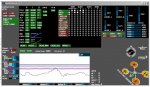
3. Habe das Board eingestellt. Danke Q-Man. Wenn ich nun die GUI starte müssen doch die Knüppelbewegungen identisch sein wie auf der rechten Seite beim GUI angezeigt wird ?.
Hatte Yaw verkehrt gehabt. Wenn ich rechts bewegt habe ist das Display nach links gewandert. Also Revers und dann ist alles OK.
Dann dürfte ich doch den ersten Startversuch starten. Oder muss ich noch etwas beachten ?
1. Ich habe ein normales langes Display und ein Oled Display für die Multiwii. Weiss jemand wie man diese an der Cirius SE 0.2 anschliessen kann und ansteuern kann. In der Config habe ich die Displays ausgeklammert und an der Platine angeschlossen neben dem Programmer Steckplatz.
2. Ist es nicht besser wenn man die Motoren direkt auf den Alurahmen montiert statt auf dem Motorträger. Denn der Motorträger lässt sich ja doch leicht biegen und das müsste man doch beim Flug bemerken.
3. Habe das Board eingestellt. Danke Q-Man. Wenn ich nun die GUI starte müssen doch die Knüppelbewegungen identisch sein wie auf der rechten Seite beim GUI angezeigt wird ?.
Hatte Yaw verkehrt gehabt. Wenn ich rechts bewegt habe ist das Display nach links gewandert. Also Revers und dann ist alles OK.
Dann dürfte ich doch den ersten Startversuch starten. Oder muss ich noch etwas beachten ?
1) Ja, das ist der serielle Anschluß. Das lange (ich tippe mal 2x16 Zeichen) Display wird dort angeschlossen. Das OLED hat ein I2C, meine ich zumindest. Es müssen in der Config.h für die Displays einige Dinge aktiviert werden. Damit habe ich mich aber noch nicht beschäftigt.
2) Der Motorträger (das Kreuz denke ich mal meinst du) läßt sich fest mit dem Motor verschrauben. Da wackelt nichts. Mach doch mal ein Bild.
3)- Denke an ein Kallibrieren des ACC.
- Ich habe die Throttle-Kurve im Config Tool so eingestellt, das ich um den Schwebepunkt (so ca1300 bei mir) den Stick in der Mitte habe und dort sehr feinfühlig regeln kann.
- Beim ersten Start langsam Gas geben, nicht das etwas nicht stimmt und er sich aufstellt.
Viel Glück!
Danke werde es versuchen und heute ein Bild machen.
Aber was Du in der Config meinst, kann ich nicht finden. Display wird angesteuert und funktioniert.
Aber was Du in der Config meinst, kann ich nicht finden. Display wird angesteuert und funktioniert.
/*************************************************************************************************/
/***************** ***************/
/**************** SECTION 1 - BASIC SETUP *******/
/***************** ***************/
/*************************************************************************************************/
/************************** The type of multicopter ****************************/
//#define GIMBAL
//#define BI
//#define TRI
//#define QUADP
#define QUADX
//#define Y4
//#define Y6
//#define HEX6
//#define HEX6X
//#define OCTOX8
//#define OCTOFLATP
//#define OCTOFLATX
//#define FLYING_WING
//#define VTAIL4
//#define AIRPLANE
//#define SINGLECOPTER
//#define DUALCOPTER
//#define HELI_120_CCPM
//#define HELI_90_DEG
/**************************** Motor minthrottle *******************************/
/* Set the minimum throttle command sent to the ESC (Electronic Speed Controller)
This is the minimum value that allow motors to run at a idle speed */
//#define MINTHROTTLE 1300 // for Turnigy Plush ESCs 10A
//#define MINTHROTTLE 1120 // for Super Simple ESCs 10A
//#define MINTHROTTLE 1064 // special ESC (simonk)
#define MINTHROTTLE 1100
/**************************** Motor maxthrottle *******************************/
/* this is the maximum value for the ESCs at full power, this value can be increased up to 2000 */
#define MAXTHROTTLE 2000
/**************************** Mincommand *******************************/
/* this is the value for the ESCs when they are not armed
in some cases, this value must be lowered down to 900 for some specific ESCs, otherwise they failed to initiate */
#define MINCOMMAND 1000
/********************************** I2C speed ************************************/
#define I2C_SPEED 100000L //100kHz normal mode, this value must be used for a genuine WMP
//#define I2C_SPEED 400000L //400kHz fast mode, it works only with some WMP clones
/*************************** Internal i2c Pullups ********************************/
/* enable internal I2C pull ups (in most cases it is better to use external pullups) */
//#define INTERNAL_I2C_PULLUPS
/**************************************************************************************/
/***************** boards and sensor definitions ******************/
/**************************************************************************************/
/*************************** Combined IMU Boards ********************************/
/* if you use a specific sensor board:
please submit any correction to this list.
Note from Alex: I only own some boards, for other boards, I'm not sure, the info was gathered via rc forums, be cautious */
//#define FFIMUv1 // first 9DOF+baro board from Jussi, with HMC5843 <- confirmed by Alex
//#define FFIMUv2 // second version of 9DOF+baro board from Jussi, with HMC5883 <- confirmed by Alex
//#define FREEIMUv1 // v0.1 & v0.2 & v0.3 version of 9DOF board from Fabio
//#define FREEIMUv03 // FreeIMU v0.3 and v0.3.1
//#define FREEIMUv035 // FreeIMU v0.3.5 no baro
//#define FREEIMUv035_MS // FreeIMU v0.3.5_MS <- confirmed by Alex
//#define FREEIMUv035_BMP // FreeIMU v0.3.5_BMP
//#define FREEIMUv04 // FreeIMU v0.4 with MPU6050, HMC5883L, MS561101BA <- confirmed by Alex
//#define FREEIMUv043 // same as FREEIMUv04 with final MPU6050 (with the right ACC scale)
//#define NANOWII // the smallest multiwii FC based on MPU6050 + pro micro based proc <- confirmed by Alex
//#define PIPO // 9DOF board from erazz
//#define QUADRINO // full FC board 9DOF+baro board from witespy with BMP085 baro <- confirmed by Alex
//#define QUADRINO_ZOOM // full FC board 9DOF+baro board from witespy second edition
//#define QUADRINO_ZOOM_MS// full FC board 9DOF+baro board from witespy second edition <- confirmed by Alex
//#define ALLINONE // full FC board or standalone 9DOF+baro board from CSG_EU
//#define AEROQUADSHIELDv2
//#define ATAVRSBIN1 // Atmel 9DOF (Contribution by EOSBandi). requires 3.3V power.
//#define SIRIUS // Sirius Navigator IMU <- confirmed by Alex
//#define SIRIUS600 // Sirius Navigator IMU using the WMP for the gyro
//#define MINIWII // Jussi's MiniWii Flight Controller <- confirmed by Alex
//#define CITRUSv2_1 // CITRUS from qcrc.ca
//#define CHERRY6DOFv1_0
//#define DROTEK_10DOF // Drotek 10DOF with ITG3200, BMA180, HMC5883, BMP085, w or w/o LLC
//#define DROTEK_10DOF_MS // Drotek 10DOF with ITG3200, BMA180, HMC5883, MS5611, LLC
//#define DROTEK_6DOFv2 // Drotek 6DOF v2
//#define DROTEK_6DOF_MPU // Drotek 6DOF with MPU6050
//#define DROTEK_10DOF_MPU//
//#define MONGOOSE1_0 // mongoose 1.0 http://store.ckdevices.com/
//#define CRIUS_LITE // Crius MultiWii Lite
#define CRIUS_SE // Crius MultiWii SE
//#define OPENLRSv2MULTI // OpenLRS v2 Multi Rc Receiver board including ITG3205 and ADXL345
//#define BOARD_PROTO_1 // with MPU6050 + HMC5883L + MS baro
//#define BOARD_PROTO_2 // with MPU6050 + slave MAG3110 + MS baro
//#define GY_80 // Chinese 10 DOF with L3G4200D ADXL345 HMC5883L BMP085, LLC
//#define GY_85 // Chinese 9 DOF with ITG3205 ADXL345 HMC5883L LLC
//#define GY_86 // Chinese 10 DOF with MPU6050 HMC5883L MS5611, LLC
//#define INNOVWORKS_10DOF // with ITG3200, BMA180, HMC5883, BMP085 available here http://www.diymulticopter.com
//#define INNOVWORKS_6DOF // with ITG3200, BMA180 available here http://www.diymulticopter.com
//#define PROTO_DIY // 10DOF mega board
//#define IOI_MINI_MULTIWII// www.bambucopter.com
//#define Bobs_6DOF_V1 // BobsQuads 6DOF V1 with ITG3200 & BMA180
//#define Bobs_9DOF_V1 // BobsQuads 9DOF V1 with ITG3200, BMA180 & HMC5883L
//#define Bobs_10DOF_BMP_V1 // BobsQuads 10DOF V1 with ITG3200, BMA180, HMC5883L & BMP180 - BMP180 is software compatible with BMP085
//#define FLYDUINO_MPU
//#define CRIUS_AIO_PRO_V1
/*************************** independent sensors ********************************/
/* leave it commented if you already checked a specific board above */
/* I2C gyroscope */
//#define WMP
//#define ITG3200
//#define L3G4200D
//#define MPU6050 //combo + ACC
/* I2C accelerometer */
//#define NUNCHUCK // if you want to use the nunckuk connected to a WMP
//#define MMA7455
//#define ADXL345
//#define BMA020
//#define BMA180
//#define NUNCHACK // if you want to use the nunckuk as a standalone I2C ACC without WMP
//#define LIS3LV02
//#define LSM303DLx_ACC
/* I2C barometer */
//#define BMP085
//#define MS561101BA
/* I2C magnetometer */
//#define HMC5843
//#define HMC5883
//#define AK8975
//#define MAG3110
/* Sonar */ // for visualization purpose currently - no control code behind
//#define SRF02 // use the Devantech SRF i2c sensors
//#define SRF08
//#define SRF10
//#define SRF23
/* ADC accelerometer */ // for 5DOF from sparkfun, uses analog PIN A1/A2/A3
//#define ADCACC
/* individual sensor orientation */
//#define ACC_ORIENTATION(X, Y, Z) {accADC[ROLL] = Y; accADC[PITCH] = -X; accADC[YAW] = Z;}
//#define GYRO_ORIENTATION(X, Y, Z) {gyroADC[ROLL] = -Y; gyroADC[PITCH] = X; gyroADC[YAW] = Z;}
//#define MAG_ORIENTATION(X, Y, Z) {magADC[ROLL] = X; magADC[PITCH] = Y; magADC[YAW] = Z;}
/*************************************************************************************************/
/***************** ***************/
/**************** SECTION 2 - COPTER TYPE SPECIFIC OPTIONS *******/
/***************** ***************/
/*************************************************************************************************/
/******************************** TRI *********************************/
#define YAW_DIRECTION 1
//#define YAW_DIRECTION -1 // if you want to reverse the yaw correction direction
/* you can change the tricopter servo travel here */
#define TRI_YAW_CONSTRAINT_MIN 1020
#define TRI_YAW_CONSTRAINT_MAX 2000
#define TRI_YAW_MIDDLE 1500 // tail servo center pos. - use this for initial trim; later trim midpoint via LCD
/******************************** ARM/DISARM *********************************/
/* optionally disable stick combinations to arm/disarm the motors.
* In most cases one of the two options to arm/disarm via TX stick is sufficient */
#define ALLOW_ARM_DISARM_VIA_TX_YAW
#define ALLOW_ARM_DISARM_VIA_TX_ROLL
/*********************** Cam Stabilisation ***********************/
/* The following lines apply only for a pitch/roll tilt stabilization system. Uncomment the first or second line to activate it */
//#define SERVO_MIX_TILT
//#define SERVO_TILT
#define TILT_PITCH_MIN 1020 //servo travel min, don't set it below 1020
#define TILT_PITCH_MAX 2000 //servo travel max, max value=2000
#define TILT_PITCH_MIDDLE 1500 //servo neutral value
#define TILT_PITCH_PROP 10 //servo proportional (tied to angle) ; can be negative to invert movement
#define TILT_ROLL_MIN 1020
#define TILT_ROLL_MAX 2000
#define TILT_ROLL_MIDDLE 1500
#define TILT_ROLL_PROP 10
/* camera trigger function : activated via Rc Options in the GUI, servo output=A2 on promini */
//#define CAMTRIG
#define CAM_SERVO_HIGH 2000 // the position of HIGH state servo
#define CAM_SERVO_LOW 1020 // the position of LOW state servo
#define CAM_TIME_HIGH 1000 // the duration of HIGH state servo expressed in ms
#define CAM_TIME_LOW 1000 // the duration of LOW state servo expressed in ms
/*********************** Flying Wing ***********************/
/* you can change change servo orientation and servo min/max values here
valid for all flight modes, even passThrough mode
need to setup servo directions here; no need to swap servos amongst channels at rx */
#define PITCH_DIRECTION_L 1 // left servo - pitch orientation
#define PITCH_DIRECTION_R -1 // right servo - pitch orientation (opposite sign to PITCH_DIRECTION_L, if servos are mounted in mirrored orientation)
#define ROLL_DIRECTION_L 1 // left servo - roll orientation
#define ROLL_DIRECTION_R 1 // right servo - roll orientation (same sign as ROLL_DIRECTION_L, if servos are mounted in mirrored orientation)
#define WING_LEFT_MID 1500 // left servo center pos. - use this for initial trim; later trim midpoint via LCD
#define WING_RIGHT_MID 1500 // right servo center pos. - use this for initial trim; later trim midpoint via LCD
#define WING_LEFT_MIN 1020 // limit servo travel range must be inside [1020;2000]
#define WING_LEFT_MAX 2000 // limit servo travel range must be inside [1020;2000]
#define WING_RIGHT_MIN 1020 // limit servo travel range must be inside [1020;2000]
#define WING_RIGHT_MAX 2000 // limit servo travel range must be inside [1020;2000]
/*********************** Airplane ***********************/
#define SERVO_RATES {100, 100, 100, 100, 100, 100, 100, 100} // Rates in 0-100%
#define SERVO_DIRECTION { -1, 1, 1, -1, 1, 1, 1, 1 } // Invert servos by setting -1
//#define FLAPPERONS AUX4 // Mix Flaps with Aileroins.
#define FLAPPERON_EP { 1500, 1700 } // Endpooints for flaps on a 2 way switch else set {1020,2000} and program in radio.
//#define FLAPPERON_EP { 1200, 1500 } // Or Flapperons up for CrowMix
#define FLAPPERON_INVERT { 1, -1 } // Change direction om flapperons { Wing1, Wing2 }
//#define FLAPS AUX4 // Traditional Flaps on A2 invert with SERVO_DIRECTION servo[2).
#define FLAP_EP { 1500, 1900 } // Endpooints for flaps on a 2 way switch else set {1020,2000} and program in radio.
//#define FLAPSPEED 3 // Make flaps move slowm Higher value is Higher Speed.
/*********************** Common for Heli & Airplane ***********************/
//#define D12_POWER // Use D12 on PROMINI to power sensors. Will disable servo[4] on D12
#define SERVO_OFFSET { 0, 0, 0, 0, 0, 0, 0, 0 } // Adjust Servo MID Offset & Swash angles
// Selectable channels:= ROLL,PITCH,THROTTLE,YAW,AUX1,AUX2,AUX3,AUX4
/*********************** Heli ***********************/
/* Channel to control CollectivePitch */
#define COLLECTIVE_PITCH THROTTLE
/* Set Maximum available movement for the servos. Depending on model */
#define SERVO_ENDPOINT_HIGH {2000,2000,2000,2000,2000,2000,2000,2000};
#define SERVO_ENDPOINT_LOW {1020,1020,1020,1020,1020,1020,1020,1020};
/* Limit the range of Collective Pitch. 100% is Full Range each way and position for Zero Pitch */
#define COLLECTIVE_RANGE { 80, 1500, 80 }// {Min%, ZeroPitch, Max%}.
#define YAW_CENTER 1500 // Use servo[5] SERVO_ENDPOINT_HIGH/LOW for the endpoits.
#define YAWMOTOR 0 // If a motor is useed as YAW Set to 1 else set to 0.
/* Servo mixing for heli 120 Use 1/10 fractions (ex.5 = 5/10 = 1/2)
{Coll,Nick,Roll} */
#define SERVO_NICK { +10, -10, -0 }
#define SERVO_LEFT { +10, +5, +10 }
#define SERVO_RIGHT { +10, +5, -10 }
/* Servo mixing for heli 90
{Coll,Nick,Roll} */
#define SERVO_DIRECTIONS { +1, -1, -1 } // -1 will invert servo
/* Limit Maximum controll for Roll & Nick in 0-100% */
#define CONTROLL_RANGE { 100, 100 } // { ROLL,PITCH }
/* use servo code to drive the throttle output. You want this for analog servo driving the throttle on IC engines.
if inactive, throttle output will be treated as a motor output, so it can drive an ESC */
//#define HELI_USE_SERVO_FOR_THROTTLE
/*********************** Single and DualCopter Settings ***********************/
/* Change to -1 to reverse servomovement per axis
Servosettings for SingleCopter */
#define SINGLECOPTRER_YAW {1, 1, 1, 1} // Left, Right,Front,Rear
#define SINGLECOPTRER_SERVO {1,-1, 1,-1} // Pitch,Pitch,Roll, Roll
/* Servosettings for DualCopter */
#define DUALCOPTER_SERVO {1,1} //Pitch,Roll
/* Use SERVO_OFFSET and SERVO_RATES in Heli and Airplane section for centering and endpoints */
/*************************************************************************************************/
/***************** ***************/
/**************** SECTION 3 - RC SYSTEM SETUP *******/
/***************** ***************/
/*************************************************************************************************/
/* note: no need to uncomment something in this section if you use a standard receiver */
/**************************************************************************************/
/******** special receiver types ********************/
/**************************************************************************************/
/**************************** PPM Sum Reciver ***********************************/
/* The following lines apply only for specific receiver with only one PPM sum signal, on digital PIN 2
Select the right line depending on your radio brand. Feel free to modify the order in your PPM order is different */
//#define SERIAL_SUM_PPM PITCH,YAW,THROTTLE,ROLL,AUX1,AUX2,AUX3,AUX4 //For Graupner/Spektrum
//#define SERIAL_SUM_PPM ROLL,PITCH,THROTTLE,YAW,AUX1,AUX2,AUX3,AUX4 //For Robe/Hitec/Futaba
//#define SERIAL_SUM_PPM PITCH,ROLL,THROTTLE,YAW,AUX1,AUX2,AUX3,AUX4 //For some Hitec/Sanwa/Others
/********************** Spektrum Satellite Reciver *******************************/
/* The following lines apply only for Spektrum Satellite Receiver
Spektrum Satellites are 3V devices. DO NOT connect to 5V!
For MEGA boards, attach sat grey wire to RX1, pin 19. Sat black wire to ground. Sat orange wire to Mega board's 3.3V (or any other 3V to 3.3V source).
For PROMINI, attach sat grey to RX0. Attach sat black to ground. */
//#define SPEKTRUM 1024
//#define SPEKTRUM 2048
/******************************* SBUS RECIVER ************************************/
/* The following line apply only for Futaba S-Bus Receiver on MEGA boards at RX1 only (Serial 1).
You have to invert the S-Bus-Serial Signal e.g. with a Hex-Inverter like IC SN74 LS 04 */
//#define SBUS
/******************* RC signal from the serial port via Multiwii Serial Protocol *********/
//#define RCSERIAL
/*************************************************************************************************/
/***************** ***************/
/**************** SECTION 4 - ALTERNATE CPUs & BOARDS *******/
/***************** ***************/
/*************************************************************************************************/
/**************************************************************************************/
/******** Promini Specifig Settings ********************/
/**************************************************************************************/
/************************** Hexa Motor 5 & 6 Pins *******************************/
/* PIN A0 and A1 instead of PIN D5 & D6 for 6 motors config and promini config
This mod allow the use of a standard receiver on a pro mini
(no need to use a PPM sum receiver) */
//#define A0_A1_PIN_HEX
/********************************* Aux 2 Pin ***********************************/
/* possibility to use PIN8 or PIN12 as the AUX2 RC input (only one, not both)
it deactivates in this case the POWER PIN (pin 12) or the BUZZER PIN (pin 8) */
//#define RCAUXPIN8
#define RCAUXPIN12
/**************************************************************************************/
/***************** Teensy 2.0 Support ******************/
/**************************************************************************************/
/* uncomment this if you use a teensy 2.0 with teensyduino
it needs to run at 16MHz */
//#define TEENSY20
/**************************************************************************************/
/******** Settings for ProMicro, Leonardo and other Atmega32u4 Boards ***********/
/**************************************************************************************/
/********************************* pin Layout **********************************/
/* activate this for a better pinlayout if all pins can be used => not possible on ProMicro */
//#define A32U4ALLPINS
/********************************** PWM Setup **********************************/
/* activate all 6 hardware PWM outputs Motor 5 = D11 and 6 = D13.
note: not possible on the sparkfun promicro (pin 11 & 13 are not broken out there)
if activated:
Motor 1-6 = 10-bit hardware PWM
Motor 7-8 = 8-bit Software PWM
Servos = 8-bit Software PWM
if deactivated:
Motor 1-4 = 10-bit hardware PWM
Motor 5-8 = 10-bit Software PWM
Servos = 10-bit Software PWM */
//#define HWPWM6
/********************************** Aux 2 Pin **********************************/
/* AUX2 pin on pin RXO */
//#define RCAUX2PINRXO
/* aux2 pin on pin D17 (RXLED) */
//#define RCAUX2PIND17
/********************************** Buzzer Pin **********************************/
/* this moves the Buzzer pin from TXO to D8 for use with ppm sum or spectrum sat. RX (not needed if A32U4ALLPINS is active) */
//#define D8BUZZER
/*********************** Promicro version related ****************************/
/* Inverted status LED for Promicro ver 10 */
//#define PROMICRO10
/*************************************************************************************************/
/***************** ***************/
/**************** SECTION 5 - ALTERNATE SETUP *******/
/***************** ***************/
/*************************************************************************************************/
/****** Serial com speed *********************************/
/* This is the speed of the serial interface */
#define SERIAL_COM_SPEED 115200
/* interleaving delay in micro seconds between 2 readings WMP/NK in a WMP+NK config
if the ACC calibration time is very long (20 or 30s), try to increase this delay up to 4000
it is relevent only for a conf with NK */
#define INTERLEAVING_DELAY 3000
/* when there is an error on I2C bus, we neutralize the values during a short time. expressed in microseconds
it is relevent only for a conf with at least a WMP */
#define NEUTRALIZE_DELAY 100000
/**************************************************************************************/
/******** Gyro filters ********************/
/**************************************************************************************/
/********************* Lowpass filter for some gyros ****************************/
/* ITG3200 & ITG3205 Low pass filter setting. In case you cannot eliminate all vibrations to the Gyro, you can try
to decrease the LPF frequency, only one step per try. As soon as twitching gone, stick with that setting.
It will not help on feedback wobbles, so change only when copter is randomly twiching and all dampening and
balancing options ran out. Uncomment only one option!
IMPORTANT! Change low pass filter setting changes PID behaviour, so retune your PID's after changing LPF.*/
//#define ITG3200_LPF_256HZ // This is the default setting, no need to uncomment, just for reference
//#define ITG3200_LPF_188HZ
//#define ITG3200_LPF_98HZ
//#define ITG3200_LPF_42HZ
//#define ITG3200_LPF_20HZ
//#define ITG3200_LPF_10HZ // Use this only in extreme cases, rather change motors and/or props
/* MPU6050 Low pass filter setting. In case you cannot eliminate all vibrations to the Gyro, you can try
to decrease the LPF frequency, only one step per try. As soon as twitching gone, stick with that setting.
It will not help on feedback wobbles, so change only when copter is randomly twiching and all dampening and
balancing options ran out. Uncomment only one option!
IMPORTANT! Change low pass filter setting changes PID behaviour, so retune your PID's after changing LPF.*/
//#define MPU6050_LPF_256HZ // This is the default setting, no need to uncomment, just for reference
//#define MPU6050_LPF_188HZ
//#define MPU6050_LPF_98HZ
//#define MPU6050_LPF_42HZ
//#define MPU6050_LPF_20HZ
//#define MPU6050_LPF_10HZ
//#define MPU6050_LPF_5HZ // Use this only in extreme cases, rather change motors and/or props
/****** Gyro smoothing **********************************/
/* GYRO_SMOOTHING. In case you cannot reduce vibrations _and_ _after_ you have tried the low pass filter options, you
may try this gyro smoothing via averaging. Not suitable for multicopters!
Good results for helicopter, airplanes and flying wings (foamies) with lots of vibrations.*/
//#define GYRO_SMOOTHING {20, 20, 3} // separate averaging ranges for roll, pitch, yaw
/************************ Moving Average Gyros **********************************/
//#define MMGYRO // Active Moving Average Function for Gyros
//#define MMGYROVECTORLENGHT 10 // Lenght of Moving Average Vector
/* Moving Average ServoGimbal Signal Output */
//#define MMSERVOGIMBAL // Active Output Moving Average Function for Servos Gimbal
//#define MMSERVOGIMBALVECTORLENGHT 32 // Lenght of Moving Average Vector
/*************************************************************************************************/
/***************** ***************/
/**************** SECTION 6 - OPTIONAL FEATURES *******/
/***************** ***************/
/*************************************************************************************************/
/* Pseudo-derivative conrtroller for level mode (experimental)
Additional information: http://www.multiwii.com/forum/viewtopic.php?f=8&t=503 */
//#define LEVEL_PDF
/******** Failsave settings ********************/
/* Failsafe check pulse on THROTTLE channel. If the pulse is OFF (on only THROTTLE or on all channels) the failsafe procedure is initiated.
After FAILSAVE_DELAY time of pulse absence, the level mode is on (if ACC or nunchuk is avaliable), PITCH, ROLL and YAW is centered
and THROTTLE is set to FAILSAVE_THR0TTLE value. You must set this value to descending about 1m/s or so for best results.
This value is depended from your configuration, AUW and some other params.
Next, afrer FAILSAVE_OFF_DELAY the copter is disarmed, and motors is stopped.
If RC pulse coming back before reached FAILSAVE_OFF_DELAY time, after the small quard time the RC control is returned to normal.
If you use serial sum PPM, the sum converter must completly turn off the PPM SUM pusles for this FailSafe functionality.*/
//#define FAILSAFE // uncomment to activate the failsafe function
#define FAILSAVE_DELAY 10 // Guard time for failsafe activation after signal lost. 1 step = 0.1sec - 1sec in example
#define FAILSAVE_OFF_DELAY 200 // Time for Landing before motors stop in 0.1sec. 1 step = 0.1sec - 20sec in example
#define FAILSAVE_THROTTLE (MINTHROTTLE + 200) // Throttle level used for landing - may be relative to MINTHROTTLE - as in this case
/***************** DFRobot LED RING *********************************/
/* I2C DFRobot LED RING communication */
//#define LED_RING
/******************************** LED FLASHER ***********************************/
//#define LED_FLASHER
//#define LED_FLASHER_DDR DDRB
//#define LED_FLASHER_PORT PORTB
//#define LED_FLASHER_BIT PORTB4
//#define LED_FLASHER_SEQUENCE ( (uint8_t) 0 )
// create double flashes
//#define LED_FLASHER_SEQUENCE_ARMED ( (uint8_t) (1<<0 | 1<<2) )
// full illumination
//#define LED_FLASHER_SEQUENCE_MAX 0xFF
/******************************* Landing lights *********************************/
/* Landing lights
Use an output pin to control landing lights.
They can be switched automatically when used in conjunction
with altitude data from a sonar unit. */
//#define LANDING_LIGHTS_DDR DDRC
//#define LANDING_LIGHTS_PORT PORTC
//#define LANDING_LIGHTS_BIT PORTC0
/* altitude above ground (in cm) as reported by sonar */
//#define LANDING_LIGHTS_AUTO_ALTITUDE 50
/************************* INFLIGHT ACC Calibration *****************************/
/* This will activate the ACC-Inflight calibration if unchecked */
//#define INFLIGHT_ACC_CALIBRATION
/************************** Disable WMP power pin *******************************/
/* disable use of the POWER PIN
(allready done if the option RCAUXPIN12 is selected) */
//#define DISABLE_POWER_PIN
/**************************************************************************************/
/*********************** TX-related **************************/
/**************************************************************************************/
/* introduce a deadband around the stick center
Must be greater than zero, comment if you dont want a deadband on roll, pitch and yaw */
//#define DEADBAND 6
/* defines the neutral zone of throttle stick during altitude hold, default setting is
+/-20 uncommend and change the value below if you want to change it. */
//#define ALT_HOLD_THROTTLE_NEUTRAL_ZONE 20
/**************************************************************************************/
/*********************** GPS **************************/
/**************************************************************************************/
/* GPS using a SERIAL port
only available on MEGA boards (this might be possible on 328 based boards in the future)
if enabled, define here the Arduino Serial port number and the UART speed
note: only the RX PIN is used, the GPS is not configured by multiwii
the GPS must be configured to output GGA and RMC NMEA sentences (which is generally the default conf for most GPS devices)
at least 5Hz update rate. uncomment the first line to select the GPS serial port of the arduino */
//#define GPS_SERIAL 2 // should be 2 for flyduino v2. It's the serial port number on arduino MEGA
#define GPS_BAUD 115200
//#define GPS_PROMINI_SERIAL 57600 // Will Autosense if GPS is connected when ardu boots
/* I2C GPS device made with an independant arduino + GPS device
including some navigation functions
contribution from EOSBandi http://code.google.com/p/i2c-gps-nav/
You have to use at least I2CGpsNav code r33 */
//#define I2C_GPS
/* I2C GPS device made with an indeedent ATTiny[24]313 + GPS device and
optional sonar device. https://github.com/wertarbyte/tiny-gps/ */
/* get GPS data from Tiny-GPS */
//#define TINY_GPS
/* get sonar data from Tiny-GPS */
//#define TINY_GPS_SONAR
/* indicate a valid GPS fix with at least 5 satellites by flashing the LED? */
#define GPS_LED_INDICATOR
/* GPS data readed from OSD -- still need some more code to work */
//#define GPS_FROM_OSD
//#define USE_MSP_WP //Enables the MSP_WP command, which is used by WinGUI to display and log Home and Poshold positions
//Uncomment it if you are planning to use WinGUI - Will cost +208 bytes of Flash
//#define DONT_RESET_HOME_AT_ARM // HOME position is reset at every arm, uncomment it to prohibit it (you can set home position with GyroCalibration)
/* GPS navigation can control the heading */
#define NAV_CONTROLS_HEADING true // copter faces toward the navigation point, maghold must be enabled for it
#define NAV_TAIL_FIRST false // true - copter comes in with tail first
#define NAV_SET_TAKEOFF_HEADING true // true - when copter arrives to home position it rotates it's head to takeoff direction
/* Get your magnetic decliniation from here : http://magnetic-declination.com/
Convert the degree+minutes into decimal degree by ==> degree+minutes*(1/60)
Note the sign on declination it could be negative or positive (WEST or EAST) */
//#define MAG_DECLINIATION 3.96f //For Budapest Hungary.
#define MAG_DECLINIATION 0.0f
#define GPS_FILTERING // add a 5 element moving average filter to GPS coordinates, helps eliminate gps noise but adds latency comment out to disable
#define GPS_LOW_SPEED_D_FILTER // below .5m/s speed ignore D term for POSHOLD_RATE, theoretically this also removed D term induced noise commnent out to disable
#define GPS_WP_RADIUS 200 // if we are within this distance to a waypoint then we consider it reached (distance is in cm)
#define NAV_SLEW_RATE 30 // Adds a rate control to nav output, will smoothen out nav angle spikes
/**************************************************************************************/
/*********************** LCD/OLED - display settings *********************/
/**************************************************************************************/
/* uncomment this line if you plan to use a LCD or OLED */
#define LCD_CONF
/* to include setting the aux switches for AUX1 -> AUX4 via LCD */ //to review (activate[] is now 16 bit long)
//#define LCD_CONF_AUX
/* if program gets too large (>32k), need to exclude some functionality */
/* uncomment to suppress some unwanted aux3 aux4 items in config menu (only useful if LCD_CONF_AUX is enabled) */
//#define SUPPRESS_LCD_CONF_AUX34
/***************************** The type of LCD **********************************/
/* choice of LCD attached for configuration and telemetry, see notes below */
#define LCD_SERIAL3W // Alex' initial variant with 3 wires, using rx-pin for transmission @9600 baud fixed
//#define LCD_TEXTSTAR // SERIAL LCD: Cat's Whisker LCD_TEXTSTAR Module CW-LCD-02 (Which has 4 input keys for selecting menus)
//#define LCD_VT100 // SERIAL LCD: vt100 compatible terminal emulation (blueterm, putty, etc.)
//#define LCD_ETPP // I2C LCD: Eagle Tree Power Panel LCD, which is i2c (not serial)
//#define LCD_LCD03 // I2C LCD: LCD03, which is i2c
//#define OLED_I2C_128x64 // I2C LCD: OLED http://www.multiwii.com/forum/viewtopic.php?f=7&t=1350
/****************************** Logo settings ***********************************/
//#define SUPPRESS_OLED_I2C_128x64LOGO // suppress display of OLED logo to save memory
/* style of display - AUTODETECTED via LCD_ setting - only activate to overwrite defaults */
#define DISPLAY_2LINES
//#define DISPLAY_MULTILINE
//#define MULTILINE_PRE 2 // multiline configMenu # pref lines
//#define MULTILINE_POST 6 // multiline configMenu # post lines
/******************************** Navigation ***********************************/
/* keys to navigate the LCD menu (preset to LCD_TEXTSTAR key-depress codes)*/
#define LCD_MENU_PREV 'a'
#define LCD_MENU_NEXT 'c'
#define LCD_VALUE_UP 'd'
#define LCD_VALUE_DOWN 'b'
#define LCD_MENU_SAVE_EXIT 's'
#define LCD_MENU_ABORT 'x'
/* To use an LCD03 for configuration:
http://www.robot-electronics.co.uk/htm/Lcd03tech.htm
Remove the jumper on its back to set i2c control.
VCC to +5V VCC (pin1 from top)
SDA - Pin A4 Mini Pro - Pin 20 Mega (pin2 from top)
SCL - Pin A5 Mini Pro - Pin 21 Mega (pin3 from top)
GND to Ground (pin4 from top)*/
/* To use an Eagle Tree Power Panel LCD for configuration:
White wire to Ground
Red wire to +5V VCC (or to the WMP power pin, if you prefer to reset everything on the bus when WMP resets)
Yellow wire to SDA - Pin A4 Mini Pro - Pin 20 Mega
Brown wire to SCL - Pin A5 Mini Pro - Pin 21 Mega */
/* Cat's whisker LCD_TEXTSTAR LCD
Pleae note this display needs a full 4 wire connection to (+5V, Gnd, RXD, TXD )
Configure display as follows: 115K baud, and TTL levels for RXD and TXD, terminal mode
NO rx / tx line reconfiguration, use natural pins.
The four buttons sending 'A', 'B', 'C', 'D' are supported for configuration navigation and request of telemetry pages 1-4 */
/**************************************************************************************/
/*********************** telemetry **************************/
/**************************************************************************************/
/* to monitor system values (battery level, loop time etc. with LCD enable this
note: for now you must send single characters to request different pages
Buttons toggle request for page on/off
The active page on the LCD does get updated automatically
Easy to use with Terminal application or display like LCD - if available uses the 4 preconfigured buttons to send 'A', 'B', 'C', 'D' */
/******************************** Activation ***********************************/
//#define LCD_TELEMETRY
/* to enable automatic hopping between a choice of telemetry pages uncomment this.
This may be useful if your LCD has no buttons or the sending is broken
hopping is activated and deactivated in unarmed mode with throttle=low & roll=left & pitch=forward
set it to the sequence of telemetry pages you want to see
2 line displays support pages 1-9
multiline displays support pages 1-5 */
//#define LCD_TELEMETRY_AUTO "123452679" // pages 1 to 7 in ascending order
//#define LCD_TELEMETRY_AUTO "212232425262729" // strong emphasis on page 2
/* same as above, but manual stepping sequence; requires
stick input (throttle=low & roll=right & pitch=forward) to
step through each defined telemetry page */
//#define LCD_TELEMETRY_STEP "0123456789" // must begin with 0
/* on telemetry page B (2) it gives a bar graph which shows how much voltage battery has left. Range from 0 to 12 Volt is not very informative
so we try do define a meaningful range. For a 3S battery we define full=12,6V and calculate how much it is above first warning level
Example: 12.6V - VBATLEVEL1_3S (for me = 126 - 102 = 24) */
#define VBATREF 24
/* if program gets too large (>32k), need to exclude some functionality
uncomment to suppress some unwanted telemetry pages (only useful if telemetry is enabled) */
//#define SUPPRESS_TELEMETRY_PAGE_1
//#define SUPPRESS_TELEMETRY_PAGE_2
//#define SUPPRESS_TELEMETRY_PAGE_3
//#define SUPPRESS_TELEMETRY_PAGE_4
//#define SUPPRESS_TELEMETRY_PAGE_5
//#define SUPPRESS_TELEMETRY_PAGE_6
//#define SUPPRESS_TELEMETRY_PAGE_7
//#define SUPPRESS_TELEMETRY_PAGE_8
//#define SUPPRESS_TELEMETRY_PAGE_9
/********************************************************************/
/**** Buzzer ****/
/********************************************************************/
//#define BUZZER
//#define RCOPTIONSBEEP //uncomment this if you want the buzzer to beep at any rcOptions change on channel Aux1 to Aux4
//#define ARMEDTIMEWARNING 330 // Trigger an alarm after a certain time of being armed to save you lipo (if your TX does not have a countdown)
/********************************************************************/
/**** battery voltage monitoring ****/
/********************************************************************/
/* for V BAT monitoring
after the resistor divisor we should get [0V;5V]->[0;1023] on analog V_BATPIN
with R1=33k and R2=51k
vbat = [0;1023]*16/VBATSCALE
must be associated with #define BUZZER ! */
//#define VBAT // uncomment this line to activate the vbat code
#define VBATSCALE 131 // change this value if readed Battery voltage is different than real voltage
#define VBATLEVEL1_3S 107 // 10,7V
#define VBATLEVEL2_3S 103 // 10,3V
#define VBATLEVEL3_3S 99 // 9.9V
#define NO_VBAT 16 // Avoid beeping without any battery
/********************************************************************/
/**** powermeter (battery capacity monitoring) ****/
/********************************************************************/
/* enable monitoring of the power consumption from battery (think of mAh)
allows to set alarm value in GUI or via LCD
Two options:
1 - soft: - (good results +-5% for plush and mystery ESCs @ 2S and 3S, not good with SuperSimple ESC
00. relies on your combo of battery type (Voltage, cpacity), ESC, ESC settings, motors, props and multiwii cycle time
01. set POWERMETER soft. Uses PLEVELSCALE = 50, PLEVELDIV = PLEVELDIVSOFT = 5000
0. output is a value that linearily scales to power (mAh)
1. get voltage reading right first
2. start with freshly charged battery
3. go fly your typical flight (routine and duration)
4. at end connect to GUI or LCD and read the power value; write it down (example 4711)
5. charge battery, write down amount of energy needed (example 722 mAh)
6. compute alarm value for desired power threshold (example 750 mAh : alarm = 4711 / 722 * 750)
7. set alarm value in GUI or LCD
8. enjoy your new battery alarm - possibly repeat steps 2 .. 7
9. if you want the numbers to represent your mAh value, you must change PLEVELDIV
2 - hard: - (uses hardware sensor, after configuration gives reasonable results
00. uses analog pin 2 to read voltage output from sensor.
01. set POWERMETER hard. Uses PLEVELSCALE = 50
02. install low path filter for 25 Hz to sensor input
03. check your average cycle time. If not close to 3ms, then you must change PLEVELDIV accordingly
1. compute PLEVELDIV for your sensor (see below for insturctions)
2. set PLEVELDIVSOFT to 5000 ( to use LOG_VALUES for individual motor comparison)
3. attach, set PSENSORNULL and PINT2mA
4. configure, compile, upload, set alarm value in GUI or LCD
3. enjoy true readings of mAh consumed
set POWERMETER to "soft" (1) or "hard" (2) depending on sensor you want to utilize */
//#define POWERMETER_SOFT
//#define POWERMETER_HARD
/* the sum of all powermeters ranges from [0:60000 e4] theoretically.
the alarm level from eeprom is out of [0:255], so we multipy alarm level with PLEVELSCALE and with 1e4 before comparing
PLEVELSCALE is the step size you can use to set alarm */
#define PLEVELSCALE 50 // if you change this value for other granularity, you must search for comments in code to change accordingly
/* larger PLEVELDIV will get you smaller value for power (mAh equivalent) */
#define PLEVELDIV 5000 // default for soft - if you lower PLEVELDIV, beware of overrun in uint32 pMeter
#define PLEVELDIVSOFT PLEVELDIV // for soft always equal to PLEVELDIV; for hard set to 5000
//#define PLEVELDIV 1361L // to convert the sum into mAh divide by this value
/* amploc 25A sensor has 37mV/A
arduino analog resolution is 4.9mV per unit; units from [0..1023]
sampling rate 20ms, approx 19977 micro seconds
PLEVELDIV = 37 / 4.9 * 10e6 / 18000 * 3600 / 1000 = 1361L
set to analogRead() value for zero current */
#define PSENSORNULL 510 // for I=0A my sensor gives 1/2 Vss; that is approx 2.49Volt
#define PINT2mA 13 // for telemtry display: one integer step on arduino analog translates to mA (example 4.9 / 37 * 100
/*************************************************************************************************/
/***************** ***************/
/**************** SECTION 7 - TUNING & DEVELOPER **************/
/***************** ***************/
/*************************************************************************************************/
/**************************************************************************************/
/******** special ESC with extended range [0-2000] microseconds ********************/
/**************************************************************************************/
//#define EXT_MOTOR_RANGE
/**************************************************************************************/
/*********************** motor, servo and other presets ***********************/
/**************************************************************************************/
/* motors will not spin when the throttle command is in low position
this is an alternative method to stop immediately the motors */
//#define MOTOR_STOP
/* some radios have not a neutral point centered on 1500. can be changed here */
#define MIDRC 1500
/*********************** Servo Refreshrates ***********************/
/* Default 50Hz Servo refresh rate*/
#define SERVO_RFR_50HZ
/* up to 160Hz servo refreshrate .. works with the most analog servos*/
//#define SERVO_RFR_160HZ
/* up to 300Hz refreshrate it is as fast as possible (100-300Hz depending on the cound of used servos and the servos state).
for use with digital servos
dont use it with analog servos! thay may get damage. (some will work but be careful) */
//#define SERVO_RFR_300HZ
/*********************** HW PWM Servos ***********************/
/* HW PWM Gimbal for Arduino Mega.. moves:
Pitch = pin 44
Roll = pin 45
this reduces the PWM resolution for all other servos to 8 bit */
//#define MEGA_HW_GIMBAL
/********************************************************************/
/**** IMU complimentary filter tuning ****/
/********************************************************************/
/* Set the Low Pass Filter factor for ACC
Increasing this value would reduce ACC noise (visible in GUI), but would increase ACC lag time
Comment this out if you want to set a specific coeff (non default)*/
//#define ACC_LPF_FACTOR 100
/* Set the Low Pass Filter factor for Magnetometer
Increasing this value would reduce Magnetometer noise (not visible in GUI), but would increase Magnetometer lag time
Comment this out if you want to set a specific coeff (non default)*/
//#define MG_LPF_FACTOR 4
/* Set the Gyro Weight for Gyro/Acc complementary filter
Increasing this value would reduce and delay Acc influence on the output of the filter
Comment this out if you want to set a specific coeff (non default)*/
//#define GYR_CMPF_FACTOR 400.0f
/* Set the Gyro Weight for Gyro/Magnetometer complementary filter
Increasing this value would reduce and delay Magnetometer influence on the output of the filter
Comment this out if you want to set a specific coeff (non default)*/
//#define GYR_CMPFM_FACTOR 200.0f
/********************************************************************/
/**** diagnostics ****/
/********************************************************************/
/* to log values like max loop time and others to come
logging values are visible via LCD config
set to 2, if you want powerconsumption on a per motor basis (this uses the big array and is a memory hog, if POWERMETER <> PM_SOFT) */
//#define LOG_VALUES 1
/* to add debugging code
not needed and not recommended for normal operation
will add extra code that may slow down the main loop or make copter non-flyable */
//#define DEBUG
/* Use this to trigger LCD configuration without a TX - only for debugging - do NOT fly with this activated */
//#define LCD_CONF_DEBUG
/* Use this to trigger telemetry without a TX - only for debugging - do NOT fly with this activated */
//#define LCD_TELEMETRY_DEBUG //This form rolls between all screens, LCD_TELEMETRY_AUTO must also be defined.
//#define LCD_TELEMETRY_DEBUG 6 //This form stays on the screen specified.
/********************************************************************/
/**** ESCs calibration ****/
/********************************************************************/
/* to calibrate all ESCs connected to MWii at the same time (useful to avoid unplugging/re-plugging each ESC)
Warning: this creates a special version of MultiWii Code
You cannot fly with this special version. It is only to be used for calibrating ESCs
Read How To at http://code.google.com/p/multiwii/wiki/ESCsCalibration */
#define ESC_CALIB_LOW MINCOMMAND
#define ESC_CALIB_HIGH 2000
//#define ESC_CALIB_CANNOT_FLY // uncomment to activate
/**** internal frequencies ****/
/* frequenies for rare cyclic actions in the main loop, depend on cycle time
time base is main loop cycle time - a value of 6 means to trigger the action every 6th run through the main loop
example: with cycle time of approx 3ms, do action every 6*3ms=18ms
value must be [1; 65535] */
#define LCD_TELEMETRY_FREQ 23 // to send telemetry data over serial 23 <=> 60ms <=> 16Hz (only sending interlaced, so 8Hz update rate)
#define LCD_TELEMETRY_AUTO_FREQ 667 // to step to next telemetry page 667 <=> 2s
#define PSENSORFREQ 6 // to read hardware powermeter sensor 6 <=> 18ms
#define VBATFREQ PSENSORFREQ // to read battery voltage - keep equal to PSENSORFREQ unless you know what you are doing
/********************************************************************/
/**** Regression testing ****/
/********************************************************************/
/* for development only:
to allow for easier and reproducable config sets for test compiling, different sets of config parameters are kept
together. This is meant to help detecting compile time errors for various features in a coordinated way.
It is not meant to produce your flying firmware
To use:
- do not set any options in config.h,
- enable with #define COPTERTEST 1, then compile
- if possible, check for the size
- repeat with other values of 2, 3, 4 etc.
*/
//#define COPTERTEST 1
/*************************************************************************************************/
/**** END OF CONFIGURABLE PARAMETERS ****/
/*************************************************************************************************/
/***************** ***************/
/**************** SECTION 1 - BASIC SETUP *******/
/***************** ***************/
/*************************************************************************************************/
/************************** The type of multicopter ****************************/
//#define GIMBAL
//#define BI
//#define TRI
//#define QUADP
#define QUADX
//#define Y4
//#define Y6
//#define HEX6
//#define HEX6X
//#define OCTOX8
//#define OCTOFLATP
//#define OCTOFLATX
//#define FLYING_WING
//#define VTAIL4
//#define AIRPLANE
//#define SINGLECOPTER
//#define DUALCOPTER
//#define HELI_120_CCPM
//#define HELI_90_DEG
/**************************** Motor minthrottle *******************************/
/* Set the minimum throttle command sent to the ESC (Electronic Speed Controller)
This is the minimum value that allow motors to run at a idle speed */
//#define MINTHROTTLE 1300 // for Turnigy Plush ESCs 10A
//#define MINTHROTTLE 1120 // for Super Simple ESCs 10A
//#define MINTHROTTLE 1064 // special ESC (simonk)
#define MINTHROTTLE 1100
/**************************** Motor maxthrottle *******************************/
/* this is the maximum value for the ESCs at full power, this value can be increased up to 2000 */
#define MAXTHROTTLE 2000
/**************************** Mincommand *******************************/
/* this is the value for the ESCs when they are not armed
in some cases, this value must be lowered down to 900 for some specific ESCs, otherwise they failed to initiate */
#define MINCOMMAND 1000
/********************************** I2C speed ************************************/
#define I2C_SPEED 100000L //100kHz normal mode, this value must be used for a genuine WMP
//#define I2C_SPEED 400000L //400kHz fast mode, it works only with some WMP clones
/*************************** Internal i2c Pullups ********************************/
/* enable internal I2C pull ups (in most cases it is better to use external pullups) */
//#define INTERNAL_I2C_PULLUPS
/**************************************************************************************/
/***************** boards and sensor definitions ******************/
/**************************************************************************************/
/*************************** Combined IMU Boards ********************************/
/* if you use a specific sensor board:
please submit any correction to this list.
Note from Alex: I only own some boards, for other boards, I'm not sure, the info was gathered via rc forums, be cautious */
//#define FFIMUv1 // first 9DOF+baro board from Jussi, with HMC5843 <- confirmed by Alex
//#define FFIMUv2 // second version of 9DOF+baro board from Jussi, with HMC5883 <- confirmed by Alex
//#define FREEIMUv1 // v0.1 & v0.2 & v0.3 version of 9DOF board from Fabio
//#define FREEIMUv03 // FreeIMU v0.3 and v0.3.1
//#define FREEIMUv035 // FreeIMU v0.3.5 no baro
//#define FREEIMUv035_MS // FreeIMU v0.3.5_MS <- confirmed by Alex
//#define FREEIMUv035_BMP // FreeIMU v0.3.5_BMP
//#define FREEIMUv04 // FreeIMU v0.4 with MPU6050, HMC5883L, MS561101BA <- confirmed by Alex
//#define FREEIMUv043 // same as FREEIMUv04 with final MPU6050 (with the right ACC scale)
//#define NANOWII // the smallest multiwii FC based on MPU6050 + pro micro based proc <- confirmed by Alex
//#define PIPO // 9DOF board from erazz
//#define QUADRINO // full FC board 9DOF+baro board from witespy with BMP085 baro <- confirmed by Alex
//#define QUADRINO_ZOOM // full FC board 9DOF+baro board from witespy second edition
//#define QUADRINO_ZOOM_MS// full FC board 9DOF+baro board from witespy second edition <- confirmed by Alex
//#define ALLINONE // full FC board or standalone 9DOF+baro board from CSG_EU
//#define AEROQUADSHIELDv2
//#define ATAVRSBIN1 // Atmel 9DOF (Contribution by EOSBandi). requires 3.3V power.
//#define SIRIUS // Sirius Navigator IMU <- confirmed by Alex
//#define SIRIUS600 // Sirius Navigator IMU using the WMP for the gyro
//#define MINIWII // Jussi's MiniWii Flight Controller <- confirmed by Alex
//#define CITRUSv2_1 // CITRUS from qcrc.ca
//#define CHERRY6DOFv1_0
//#define DROTEK_10DOF // Drotek 10DOF with ITG3200, BMA180, HMC5883, BMP085, w or w/o LLC
//#define DROTEK_10DOF_MS // Drotek 10DOF with ITG3200, BMA180, HMC5883, MS5611, LLC
//#define DROTEK_6DOFv2 // Drotek 6DOF v2
//#define DROTEK_6DOF_MPU // Drotek 6DOF with MPU6050
//#define DROTEK_10DOF_MPU//
//#define MONGOOSE1_0 // mongoose 1.0 http://store.ckdevices.com/
//#define CRIUS_LITE // Crius MultiWii Lite
#define CRIUS_SE // Crius MultiWii SE
//#define OPENLRSv2MULTI // OpenLRS v2 Multi Rc Receiver board including ITG3205 and ADXL345
//#define BOARD_PROTO_1 // with MPU6050 + HMC5883L + MS baro
//#define BOARD_PROTO_2 // with MPU6050 + slave MAG3110 + MS baro
//#define GY_80 // Chinese 10 DOF with L3G4200D ADXL345 HMC5883L BMP085, LLC
//#define GY_85 // Chinese 9 DOF with ITG3205 ADXL345 HMC5883L LLC
//#define GY_86 // Chinese 10 DOF with MPU6050 HMC5883L MS5611, LLC
//#define INNOVWORKS_10DOF // with ITG3200, BMA180, HMC5883, BMP085 available here http://www.diymulticopter.com
//#define INNOVWORKS_6DOF // with ITG3200, BMA180 available here http://www.diymulticopter.com
//#define PROTO_DIY // 10DOF mega board
//#define IOI_MINI_MULTIWII// www.bambucopter.com
//#define Bobs_6DOF_V1 // BobsQuads 6DOF V1 with ITG3200 & BMA180
//#define Bobs_9DOF_V1 // BobsQuads 9DOF V1 with ITG3200, BMA180 & HMC5883L
//#define Bobs_10DOF_BMP_V1 // BobsQuads 10DOF V1 with ITG3200, BMA180, HMC5883L & BMP180 - BMP180 is software compatible with BMP085
//#define FLYDUINO_MPU
//#define CRIUS_AIO_PRO_V1
/*************************** independent sensors ********************************/
/* leave it commented if you already checked a specific board above */
/* I2C gyroscope */
//#define WMP
//#define ITG3200
//#define L3G4200D
//#define MPU6050 //combo + ACC
/* I2C accelerometer */
//#define NUNCHUCK // if you want to use the nunckuk connected to a WMP
//#define MMA7455
//#define ADXL345
//#define BMA020
//#define BMA180
//#define NUNCHACK // if you want to use the nunckuk as a standalone I2C ACC without WMP
//#define LIS3LV02
//#define LSM303DLx_ACC
/* I2C barometer */
//#define BMP085
//#define MS561101BA
/* I2C magnetometer */
//#define HMC5843
//#define HMC5883
//#define AK8975
//#define MAG3110
/* Sonar */ // for visualization purpose currently - no control code behind
//#define SRF02 // use the Devantech SRF i2c sensors
//#define SRF08
//#define SRF10
//#define SRF23
/* ADC accelerometer */ // for 5DOF from sparkfun, uses analog PIN A1/A2/A3
//#define ADCACC
/* individual sensor orientation */
//#define ACC_ORIENTATION(X, Y, Z) {accADC[ROLL] = Y; accADC[PITCH] = -X; accADC[YAW] = Z;}
//#define GYRO_ORIENTATION(X, Y, Z) {gyroADC[ROLL] = -Y; gyroADC[PITCH] = X; gyroADC[YAW] = Z;}
//#define MAG_ORIENTATION(X, Y, Z) {magADC[ROLL] = X; magADC[PITCH] = Y; magADC[YAW] = Z;}
/*************************************************************************************************/
/***************** ***************/
/**************** SECTION 2 - COPTER TYPE SPECIFIC OPTIONS *******/
/***************** ***************/
/*************************************************************************************************/
/******************************** TRI *********************************/
#define YAW_DIRECTION 1
//#define YAW_DIRECTION -1 // if you want to reverse the yaw correction direction
/* you can change the tricopter servo travel here */
#define TRI_YAW_CONSTRAINT_MIN 1020
#define TRI_YAW_CONSTRAINT_MAX 2000
#define TRI_YAW_MIDDLE 1500 // tail servo center pos. - use this for initial trim; later trim midpoint via LCD
/******************************** ARM/DISARM *********************************/
/* optionally disable stick combinations to arm/disarm the motors.
* In most cases one of the two options to arm/disarm via TX stick is sufficient */
#define ALLOW_ARM_DISARM_VIA_TX_YAW
#define ALLOW_ARM_DISARM_VIA_TX_ROLL
/*********************** Cam Stabilisation ***********************/
/* The following lines apply only for a pitch/roll tilt stabilization system. Uncomment the first or second line to activate it */
//#define SERVO_MIX_TILT
//#define SERVO_TILT
#define TILT_PITCH_MIN 1020 //servo travel min, don't set it below 1020
#define TILT_PITCH_MAX 2000 //servo travel max, max value=2000
#define TILT_PITCH_MIDDLE 1500 //servo neutral value
#define TILT_PITCH_PROP 10 //servo proportional (tied to angle) ; can be negative to invert movement
#define TILT_ROLL_MIN 1020
#define TILT_ROLL_MAX 2000
#define TILT_ROLL_MIDDLE 1500
#define TILT_ROLL_PROP 10
/* camera trigger function : activated via Rc Options in the GUI, servo output=A2 on promini */
//#define CAMTRIG
#define CAM_SERVO_HIGH 2000 // the position of HIGH state servo
#define CAM_SERVO_LOW 1020 // the position of LOW state servo
#define CAM_TIME_HIGH 1000 // the duration of HIGH state servo expressed in ms
#define CAM_TIME_LOW 1000 // the duration of LOW state servo expressed in ms
/*********************** Flying Wing ***********************/
/* you can change change servo orientation and servo min/max values here
valid for all flight modes, even passThrough mode
need to setup servo directions here; no need to swap servos amongst channels at rx */
#define PITCH_DIRECTION_L 1 // left servo - pitch orientation
#define PITCH_DIRECTION_R -1 // right servo - pitch orientation (opposite sign to PITCH_DIRECTION_L, if servos are mounted in mirrored orientation)
#define ROLL_DIRECTION_L 1 // left servo - roll orientation
#define ROLL_DIRECTION_R 1 // right servo - roll orientation (same sign as ROLL_DIRECTION_L, if servos are mounted in mirrored orientation)
#define WING_LEFT_MID 1500 // left servo center pos. - use this for initial trim; later trim midpoint via LCD
#define WING_RIGHT_MID 1500 // right servo center pos. - use this for initial trim; later trim midpoint via LCD
#define WING_LEFT_MIN 1020 // limit servo travel range must be inside [1020;2000]
#define WING_LEFT_MAX 2000 // limit servo travel range must be inside [1020;2000]
#define WING_RIGHT_MIN 1020 // limit servo travel range must be inside [1020;2000]
#define WING_RIGHT_MAX 2000 // limit servo travel range must be inside [1020;2000]
/*********************** Airplane ***********************/
#define SERVO_RATES {100, 100, 100, 100, 100, 100, 100, 100} // Rates in 0-100%
#define SERVO_DIRECTION { -1, 1, 1, -1, 1, 1, 1, 1 } // Invert servos by setting -1
//#define FLAPPERONS AUX4 // Mix Flaps with Aileroins.
#define FLAPPERON_EP { 1500, 1700 } // Endpooints for flaps on a 2 way switch else set {1020,2000} and program in radio.
//#define FLAPPERON_EP { 1200, 1500 } // Or Flapperons up for CrowMix
#define FLAPPERON_INVERT { 1, -1 } // Change direction om flapperons { Wing1, Wing2 }
//#define FLAPS AUX4 // Traditional Flaps on A2 invert with SERVO_DIRECTION servo[2).
#define FLAP_EP { 1500, 1900 } // Endpooints for flaps on a 2 way switch else set {1020,2000} and program in radio.
//#define FLAPSPEED 3 // Make flaps move slowm Higher value is Higher Speed.
/*********************** Common for Heli & Airplane ***********************/
//#define D12_POWER // Use D12 on PROMINI to power sensors. Will disable servo[4] on D12
#define SERVO_OFFSET { 0, 0, 0, 0, 0, 0, 0, 0 } // Adjust Servo MID Offset & Swash angles
// Selectable channels:= ROLL,PITCH,THROTTLE,YAW,AUX1,AUX2,AUX3,AUX4
/*********************** Heli ***********************/
/* Channel to control CollectivePitch */
#define COLLECTIVE_PITCH THROTTLE
/* Set Maximum available movement for the servos. Depending on model */
#define SERVO_ENDPOINT_HIGH {2000,2000,2000,2000,2000,2000,2000,2000};
#define SERVO_ENDPOINT_LOW {1020,1020,1020,1020,1020,1020,1020,1020};
/* Limit the range of Collective Pitch. 100% is Full Range each way and position for Zero Pitch */
#define COLLECTIVE_RANGE { 80, 1500, 80 }// {Min%, ZeroPitch, Max%}.
#define YAW_CENTER 1500 // Use servo[5] SERVO_ENDPOINT_HIGH/LOW for the endpoits.
#define YAWMOTOR 0 // If a motor is useed as YAW Set to 1 else set to 0.
/* Servo mixing for heli 120 Use 1/10 fractions (ex.5 = 5/10 = 1/2)
{Coll,Nick,Roll} */
#define SERVO_NICK { +10, -10, -0 }
#define SERVO_LEFT { +10, +5, +10 }
#define SERVO_RIGHT { +10, +5, -10 }
/* Servo mixing for heli 90
{Coll,Nick,Roll} */
#define SERVO_DIRECTIONS { +1, -1, -1 } // -1 will invert servo
/* Limit Maximum controll for Roll & Nick in 0-100% */
#define CONTROLL_RANGE { 100, 100 } // { ROLL,PITCH }
/* use servo code to drive the throttle output. You want this for analog servo driving the throttle on IC engines.
if inactive, throttle output will be treated as a motor output, so it can drive an ESC */
//#define HELI_USE_SERVO_FOR_THROTTLE
/*********************** Single and DualCopter Settings ***********************/
/* Change to -1 to reverse servomovement per axis
Servosettings for SingleCopter */
#define SINGLECOPTRER_YAW {1, 1, 1, 1} // Left, Right,Front,Rear
#define SINGLECOPTRER_SERVO {1,-1, 1,-1} // Pitch,Pitch,Roll, Roll
/* Servosettings for DualCopter */
#define DUALCOPTER_SERVO {1,1} //Pitch,Roll
/* Use SERVO_OFFSET and SERVO_RATES in Heli and Airplane section for centering and endpoints */
/*************************************************************************************************/
/***************** ***************/
/**************** SECTION 3 - RC SYSTEM SETUP *******/
/***************** ***************/
/*************************************************************************************************/
/* note: no need to uncomment something in this section if you use a standard receiver */
/**************************************************************************************/
/******** special receiver types ********************/
/**************************************************************************************/
/**************************** PPM Sum Reciver ***********************************/
/* The following lines apply only for specific receiver with only one PPM sum signal, on digital PIN 2
Select the right line depending on your radio brand. Feel free to modify the order in your PPM order is different */
//#define SERIAL_SUM_PPM PITCH,YAW,THROTTLE,ROLL,AUX1,AUX2,AUX3,AUX4 //For Graupner/Spektrum
//#define SERIAL_SUM_PPM ROLL,PITCH,THROTTLE,YAW,AUX1,AUX2,AUX3,AUX4 //For Robe/Hitec/Futaba
//#define SERIAL_SUM_PPM PITCH,ROLL,THROTTLE,YAW,AUX1,AUX2,AUX3,AUX4 //For some Hitec/Sanwa/Others
/********************** Spektrum Satellite Reciver *******************************/
/* The following lines apply only for Spektrum Satellite Receiver
Spektrum Satellites are 3V devices. DO NOT connect to 5V!
For MEGA boards, attach sat grey wire to RX1, pin 19. Sat black wire to ground. Sat orange wire to Mega board's 3.3V (or any other 3V to 3.3V source).
For PROMINI, attach sat grey to RX0. Attach sat black to ground. */
//#define SPEKTRUM 1024
//#define SPEKTRUM 2048
/******************************* SBUS RECIVER ************************************/
/* The following line apply only for Futaba S-Bus Receiver on MEGA boards at RX1 only (Serial 1).
You have to invert the S-Bus-Serial Signal e.g. with a Hex-Inverter like IC SN74 LS 04 */
//#define SBUS
/******************* RC signal from the serial port via Multiwii Serial Protocol *********/
//#define RCSERIAL
/*************************************************************************************************/
/***************** ***************/
/**************** SECTION 4 - ALTERNATE CPUs & BOARDS *******/
/***************** ***************/
/*************************************************************************************************/
/**************************************************************************************/
/******** Promini Specifig Settings ********************/
/**************************************************************************************/
/************************** Hexa Motor 5 & 6 Pins *******************************/
/* PIN A0 and A1 instead of PIN D5 & D6 for 6 motors config and promini config
This mod allow the use of a standard receiver on a pro mini
(no need to use a PPM sum receiver) */
//#define A0_A1_PIN_HEX
/********************************* Aux 2 Pin ***********************************/
/* possibility to use PIN8 or PIN12 as the AUX2 RC input (only one, not both)
it deactivates in this case the POWER PIN (pin 12) or the BUZZER PIN (pin 8) */
//#define RCAUXPIN8
#define RCAUXPIN12
/**************************************************************************************/
/***************** Teensy 2.0 Support ******************/
/**************************************************************************************/
/* uncomment this if you use a teensy 2.0 with teensyduino
it needs to run at 16MHz */
//#define TEENSY20
/**************************************************************************************/
/******** Settings for ProMicro, Leonardo and other Atmega32u4 Boards ***********/
/**************************************************************************************/
/********************************* pin Layout **********************************/
/* activate this for a better pinlayout if all pins can be used => not possible on ProMicro */
//#define A32U4ALLPINS
/********************************** PWM Setup **********************************/
/* activate all 6 hardware PWM outputs Motor 5 = D11 and 6 = D13.
note: not possible on the sparkfun promicro (pin 11 & 13 are not broken out there)
if activated:
Motor 1-6 = 10-bit hardware PWM
Motor 7-8 = 8-bit Software PWM
Servos = 8-bit Software PWM
if deactivated:
Motor 1-4 = 10-bit hardware PWM
Motor 5-8 = 10-bit Software PWM
Servos = 10-bit Software PWM */
//#define HWPWM6
/********************************** Aux 2 Pin **********************************/
/* AUX2 pin on pin RXO */
//#define RCAUX2PINRXO
/* aux2 pin on pin D17 (RXLED) */
//#define RCAUX2PIND17
/********************************** Buzzer Pin **********************************/
/* this moves the Buzzer pin from TXO to D8 for use with ppm sum or spectrum sat. RX (not needed if A32U4ALLPINS is active) */
//#define D8BUZZER
/*********************** Promicro version related ****************************/
/* Inverted status LED for Promicro ver 10 */
//#define PROMICRO10
/*************************************************************************************************/
/***************** ***************/
/**************** SECTION 5 - ALTERNATE SETUP *******/
/***************** ***************/
/*************************************************************************************************/
/****** Serial com speed *********************************/
/* This is the speed of the serial interface */
#define SERIAL_COM_SPEED 115200
/* interleaving delay in micro seconds between 2 readings WMP/NK in a WMP+NK config
if the ACC calibration time is very long (20 or 30s), try to increase this delay up to 4000
it is relevent only for a conf with NK */
#define INTERLEAVING_DELAY 3000
/* when there is an error on I2C bus, we neutralize the values during a short time. expressed in microseconds
it is relevent only for a conf with at least a WMP */
#define NEUTRALIZE_DELAY 100000
/**************************************************************************************/
/******** Gyro filters ********************/
/**************************************************************************************/
/********************* Lowpass filter for some gyros ****************************/
/* ITG3200 & ITG3205 Low pass filter setting. In case you cannot eliminate all vibrations to the Gyro, you can try
to decrease the LPF frequency, only one step per try. As soon as twitching gone, stick with that setting.
It will not help on feedback wobbles, so change only when copter is randomly twiching and all dampening and
balancing options ran out. Uncomment only one option!
IMPORTANT! Change low pass filter setting changes PID behaviour, so retune your PID's after changing LPF.*/
//#define ITG3200_LPF_256HZ // This is the default setting, no need to uncomment, just for reference
//#define ITG3200_LPF_188HZ
//#define ITG3200_LPF_98HZ
//#define ITG3200_LPF_42HZ
//#define ITG3200_LPF_20HZ
//#define ITG3200_LPF_10HZ // Use this only in extreme cases, rather change motors and/or props
/* MPU6050 Low pass filter setting. In case you cannot eliminate all vibrations to the Gyro, you can try
to decrease the LPF frequency, only one step per try. As soon as twitching gone, stick with that setting.
It will not help on feedback wobbles, so change only when copter is randomly twiching and all dampening and
balancing options ran out. Uncomment only one option!
IMPORTANT! Change low pass filter setting changes PID behaviour, so retune your PID's after changing LPF.*/
//#define MPU6050_LPF_256HZ // This is the default setting, no need to uncomment, just for reference
//#define MPU6050_LPF_188HZ
//#define MPU6050_LPF_98HZ
//#define MPU6050_LPF_42HZ
//#define MPU6050_LPF_20HZ
//#define MPU6050_LPF_10HZ
//#define MPU6050_LPF_5HZ // Use this only in extreme cases, rather change motors and/or props
/****** Gyro smoothing **********************************/
/* GYRO_SMOOTHING. In case you cannot reduce vibrations _and_ _after_ you have tried the low pass filter options, you
may try this gyro smoothing via averaging. Not suitable for multicopters!
Good results for helicopter, airplanes and flying wings (foamies) with lots of vibrations.*/
//#define GYRO_SMOOTHING {20, 20, 3} // separate averaging ranges for roll, pitch, yaw
/************************ Moving Average Gyros **********************************/
//#define MMGYRO // Active Moving Average Function for Gyros
//#define MMGYROVECTORLENGHT 10 // Lenght of Moving Average Vector
/* Moving Average ServoGimbal Signal Output */
//#define MMSERVOGIMBAL // Active Output Moving Average Function for Servos Gimbal
//#define MMSERVOGIMBALVECTORLENGHT 32 // Lenght of Moving Average Vector
/*************************************************************************************************/
/***************** ***************/
/**************** SECTION 6 - OPTIONAL FEATURES *******/
/***************** ***************/
/*************************************************************************************************/
/* Pseudo-derivative conrtroller for level mode (experimental)
Additional information: http://www.multiwii.com/forum/viewtopic.php?f=8&t=503 */
//#define LEVEL_PDF
/******** Failsave settings ********************/
/* Failsafe check pulse on THROTTLE channel. If the pulse is OFF (on only THROTTLE or on all channels) the failsafe procedure is initiated.
After FAILSAVE_DELAY time of pulse absence, the level mode is on (if ACC or nunchuk is avaliable), PITCH, ROLL and YAW is centered
and THROTTLE is set to FAILSAVE_THR0TTLE value. You must set this value to descending about 1m/s or so for best results.
This value is depended from your configuration, AUW and some other params.
Next, afrer FAILSAVE_OFF_DELAY the copter is disarmed, and motors is stopped.
If RC pulse coming back before reached FAILSAVE_OFF_DELAY time, after the small quard time the RC control is returned to normal.
If you use serial sum PPM, the sum converter must completly turn off the PPM SUM pusles for this FailSafe functionality.*/
//#define FAILSAFE // uncomment to activate the failsafe function
#define FAILSAVE_DELAY 10 // Guard time for failsafe activation after signal lost. 1 step = 0.1sec - 1sec in example
#define FAILSAVE_OFF_DELAY 200 // Time for Landing before motors stop in 0.1sec. 1 step = 0.1sec - 20sec in example
#define FAILSAVE_THROTTLE (MINTHROTTLE + 200) // Throttle level used for landing - may be relative to MINTHROTTLE - as in this case
/***************** DFRobot LED RING *********************************/
/* I2C DFRobot LED RING communication */
//#define LED_RING
/******************************** LED FLASHER ***********************************/
//#define LED_FLASHER
//#define LED_FLASHER_DDR DDRB
//#define LED_FLASHER_PORT PORTB
//#define LED_FLASHER_BIT PORTB4
//#define LED_FLASHER_SEQUENCE ( (uint8_t) 0 )
// create double flashes
//#define LED_FLASHER_SEQUENCE_ARMED ( (uint8_t) (1<<0 | 1<<2) )
// full illumination
//#define LED_FLASHER_SEQUENCE_MAX 0xFF
/******************************* Landing lights *********************************/
/* Landing lights
Use an output pin to control landing lights.
They can be switched automatically when used in conjunction
with altitude data from a sonar unit. */
//#define LANDING_LIGHTS_DDR DDRC
//#define LANDING_LIGHTS_PORT PORTC
//#define LANDING_LIGHTS_BIT PORTC0
/* altitude above ground (in cm) as reported by sonar */
//#define LANDING_LIGHTS_AUTO_ALTITUDE 50
/************************* INFLIGHT ACC Calibration *****************************/
/* This will activate the ACC-Inflight calibration if unchecked */
//#define INFLIGHT_ACC_CALIBRATION
/************************** Disable WMP power pin *******************************/
/* disable use of the POWER PIN
(allready done if the option RCAUXPIN12 is selected) */
//#define DISABLE_POWER_PIN
/**************************************************************************************/
/*********************** TX-related **************************/
/**************************************************************************************/
/* introduce a deadband around the stick center
Must be greater than zero, comment if you dont want a deadband on roll, pitch and yaw */
//#define DEADBAND 6
/* defines the neutral zone of throttle stick during altitude hold, default setting is
+/-20 uncommend and change the value below if you want to change it. */
//#define ALT_HOLD_THROTTLE_NEUTRAL_ZONE 20
/**************************************************************************************/
/*********************** GPS **************************/
/**************************************************************************************/
/* GPS using a SERIAL port
only available on MEGA boards (this might be possible on 328 based boards in the future)
if enabled, define here the Arduino Serial port number and the UART speed
note: only the RX PIN is used, the GPS is not configured by multiwii
the GPS must be configured to output GGA and RMC NMEA sentences (which is generally the default conf for most GPS devices)
at least 5Hz update rate. uncomment the first line to select the GPS serial port of the arduino */
//#define GPS_SERIAL 2 // should be 2 for flyduino v2. It's the serial port number on arduino MEGA
#define GPS_BAUD 115200
//#define GPS_PROMINI_SERIAL 57600 // Will Autosense if GPS is connected when ardu boots
/* I2C GPS device made with an independant arduino + GPS device
including some navigation functions
contribution from EOSBandi http://code.google.com/p/i2c-gps-nav/
You have to use at least I2CGpsNav code r33 */
//#define I2C_GPS
/* I2C GPS device made with an indeedent ATTiny[24]313 + GPS device and
optional sonar device. https://github.com/wertarbyte/tiny-gps/ */
/* get GPS data from Tiny-GPS */
//#define TINY_GPS
/* get sonar data from Tiny-GPS */
//#define TINY_GPS_SONAR
/* indicate a valid GPS fix with at least 5 satellites by flashing the LED? */
#define GPS_LED_INDICATOR
/* GPS data readed from OSD -- still need some more code to work */
//#define GPS_FROM_OSD
//#define USE_MSP_WP //Enables the MSP_WP command, which is used by WinGUI to display and log Home and Poshold positions
//Uncomment it if you are planning to use WinGUI - Will cost +208 bytes of Flash
//#define DONT_RESET_HOME_AT_ARM // HOME position is reset at every arm, uncomment it to prohibit it (you can set home position with GyroCalibration)
/* GPS navigation can control the heading */
#define NAV_CONTROLS_HEADING true // copter faces toward the navigation point, maghold must be enabled for it
#define NAV_TAIL_FIRST false // true - copter comes in with tail first
#define NAV_SET_TAKEOFF_HEADING true // true - when copter arrives to home position it rotates it's head to takeoff direction
/* Get your magnetic decliniation from here : http://magnetic-declination.com/
Convert the degree+minutes into decimal degree by ==> degree+minutes*(1/60)
Note the sign on declination it could be negative or positive (WEST or EAST) */
//#define MAG_DECLINIATION 3.96f //For Budapest Hungary.
#define MAG_DECLINIATION 0.0f
#define GPS_FILTERING // add a 5 element moving average filter to GPS coordinates, helps eliminate gps noise but adds latency comment out to disable
#define GPS_LOW_SPEED_D_FILTER // below .5m/s speed ignore D term for POSHOLD_RATE, theoretically this also removed D term induced noise commnent out to disable
#define GPS_WP_RADIUS 200 // if we are within this distance to a waypoint then we consider it reached (distance is in cm)
#define NAV_SLEW_RATE 30 // Adds a rate control to nav output, will smoothen out nav angle spikes
/**************************************************************************************/
/*********************** LCD/OLED - display settings *********************/
/**************************************************************************************/
/* uncomment this line if you plan to use a LCD or OLED */
#define LCD_CONF
/* to include setting the aux switches for AUX1 -> AUX4 via LCD */ //to review (activate[] is now 16 bit long)
//#define LCD_CONF_AUX
/* if program gets too large (>32k), need to exclude some functionality */
/* uncomment to suppress some unwanted aux3 aux4 items in config menu (only useful if LCD_CONF_AUX is enabled) */
//#define SUPPRESS_LCD_CONF_AUX34
/***************************** The type of LCD **********************************/
/* choice of LCD attached for configuration and telemetry, see notes below */
#define LCD_SERIAL3W // Alex' initial variant with 3 wires, using rx-pin for transmission @9600 baud fixed
//#define LCD_TEXTSTAR // SERIAL LCD: Cat's Whisker LCD_TEXTSTAR Module CW-LCD-02 (Which has 4 input keys for selecting menus)
//#define LCD_VT100 // SERIAL LCD: vt100 compatible terminal emulation (blueterm, putty, etc.)
//#define LCD_ETPP // I2C LCD: Eagle Tree Power Panel LCD, which is i2c (not serial)
//#define LCD_LCD03 // I2C LCD: LCD03, which is i2c
//#define OLED_I2C_128x64 // I2C LCD: OLED http://www.multiwii.com/forum/viewtopic.php?f=7&t=1350
/****************************** Logo settings ***********************************/
//#define SUPPRESS_OLED_I2C_128x64LOGO // suppress display of OLED logo to save memory
/* style of display - AUTODETECTED via LCD_ setting - only activate to overwrite defaults */
#define DISPLAY_2LINES
//#define DISPLAY_MULTILINE
//#define MULTILINE_PRE 2 // multiline configMenu # pref lines
//#define MULTILINE_POST 6 // multiline configMenu # post lines
/******************************** Navigation ***********************************/
/* keys to navigate the LCD menu (preset to LCD_TEXTSTAR key-depress codes)*/
#define LCD_MENU_PREV 'a'
#define LCD_MENU_NEXT 'c'
#define LCD_VALUE_UP 'd'
#define LCD_VALUE_DOWN 'b'
#define LCD_MENU_SAVE_EXIT 's'
#define LCD_MENU_ABORT 'x'
/* To use an LCD03 for configuration:
http://www.robot-electronics.co.uk/htm/Lcd03tech.htm
Remove the jumper on its back to set i2c control.
VCC to +5V VCC (pin1 from top)
SDA - Pin A4 Mini Pro - Pin 20 Mega (pin2 from top)
SCL - Pin A5 Mini Pro - Pin 21 Mega (pin3 from top)
GND to Ground (pin4 from top)*/
/* To use an Eagle Tree Power Panel LCD for configuration:
White wire to Ground
Red wire to +5V VCC (or to the WMP power pin, if you prefer to reset everything on the bus when WMP resets)
Yellow wire to SDA - Pin A4 Mini Pro - Pin 20 Mega
Brown wire to SCL - Pin A5 Mini Pro - Pin 21 Mega */
/* Cat's whisker LCD_TEXTSTAR LCD
Pleae note this display needs a full 4 wire connection to (+5V, Gnd, RXD, TXD )
Configure display as follows: 115K baud, and TTL levels for RXD and TXD, terminal mode
NO rx / tx line reconfiguration, use natural pins.
The four buttons sending 'A', 'B', 'C', 'D' are supported for configuration navigation and request of telemetry pages 1-4 */
/**************************************************************************************/
/*********************** telemetry **************************/
/**************************************************************************************/
/* to monitor system values (battery level, loop time etc. with LCD enable this
note: for now you must send single characters to request different pages
Buttons toggle request for page on/off
The active page on the LCD does get updated automatically
Easy to use with Terminal application or display like LCD - if available uses the 4 preconfigured buttons to send 'A', 'B', 'C', 'D' */
/******************************** Activation ***********************************/
//#define LCD_TELEMETRY
/* to enable automatic hopping between a choice of telemetry pages uncomment this.
This may be useful if your LCD has no buttons or the sending is broken
hopping is activated and deactivated in unarmed mode with throttle=low & roll=left & pitch=forward
set it to the sequence of telemetry pages you want to see
2 line displays support pages 1-9
multiline displays support pages 1-5 */
//#define LCD_TELEMETRY_AUTO "123452679" // pages 1 to 7 in ascending order
//#define LCD_TELEMETRY_AUTO "212232425262729" // strong emphasis on page 2
/* same as above, but manual stepping sequence; requires
stick input (throttle=low & roll=right & pitch=forward) to
step through each defined telemetry page */
//#define LCD_TELEMETRY_STEP "0123456789" // must begin with 0
/* on telemetry page B (2) it gives a bar graph which shows how much voltage battery has left. Range from 0 to 12 Volt is not very informative
so we try do define a meaningful range. For a 3S battery we define full=12,6V and calculate how much it is above first warning level
Example: 12.6V - VBATLEVEL1_3S (for me = 126 - 102 = 24) */
#define VBATREF 24
/* if program gets too large (>32k), need to exclude some functionality
uncomment to suppress some unwanted telemetry pages (only useful if telemetry is enabled) */
//#define SUPPRESS_TELEMETRY_PAGE_1
//#define SUPPRESS_TELEMETRY_PAGE_2
//#define SUPPRESS_TELEMETRY_PAGE_3
//#define SUPPRESS_TELEMETRY_PAGE_4
//#define SUPPRESS_TELEMETRY_PAGE_5
//#define SUPPRESS_TELEMETRY_PAGE_6
//#define SUPPRESS_TELEMETRY_PAGE_7
//#define SUPPRESS_TELEMETRY_PAGE_8
//#define SUPPRESS_TELEMETRY_PAGE_9
/********************************************************************/
/**** Buzzer ****/
/********************************************************************/
//#define BUZZER
//#define RCOPTIONSBEEP //uncomment this if you want the buzzer to beep at any rcOptions change on channel Aux1 to Aux4
//#define ARMEDTIMEWARNING 330 // Trigger an alarm after a certain time of being armed to save you lipo (if your TX does not have a countdown)
/********************************************************************/
/**** battery voltage monitoring ****/
/********************************************************************/
/* for V BAT monitoring
after the resistor divisor we should get [0V;5V]->[0;1023] on analog V_BATPIN
with R1=33k and R2=51k
vbat = [0;1023]*16/VBATSCALE
must be associated with #define BUZZER ! */
//#define VBAT // uncomment this line to activate the vbat code
#define VBATSCALE 131 // change this value if readed Battery voltage is different than real voltage
#define VBATLEVEL1_3S 107 // 10,7V
#define VBATLEVEL2_3S 103 // 10,3V
#define VBATLEVEL3_3S 99 // 9.9V
#define NO_VBAT 16 // Avoid beeping without any battery
/********************************************************************/
/**** powermeter (battery capacity monitoring) ****/
/********************************************************************/
/* enable monitoring of the power consumption from battery (think of mAh)
allows to set alarm value in GUI or via LCD
Two options:
1 - soft: - (good results +-5% for plush and mystery ESCs @ 2S and 3S, not good with SuperSimple ESC
00. relies on your combo of battery type (Voltage, cpacity), ESC, ESC settings, motors, props and multiwii cycle time
01. set POWERMETER soft. Uses PLEVELSCALE = 50, PLEVELDIV = PLEVELDIVSOFT = 5000
0. output is a value that linearily scales to power (mAh)
1. get voltage reading right first
2. start with freshly charged battery
3. go fly your typical flight (routine and duration)
4. at end connect to GUI or LCD and read the power value; write it down (example 4711)
5. charge battery, write down amount of energy needed (example 722 mAh)
6. compute alarm value for desired power threshold (example 750 mAh : alarm = 4711 / 722 * 750)
7. set alarm value in GUI or LCD
8. enjoy your new battery alarm - possibly repeat steps 2 .. 7
9. if you want the numbers to represent your mAh value, you must change PLEVELDIV
2 - hard: - (uses hardware sensor, after configuration gives reasonable results
00. uses analog pin 2 to read voltage output from sensor.
01. set POWERMETER hard. Uses PLEVELSCALE = 50
02. install low path filter for 25 Hz to sensor input
03. check your average cycle time. If not close to 3ms, then you must change PLEVELDIV accordingly
1. compute PLEVELDIV for your sensor (see below for insturctions)
2. set PLEVELDIVSOFT to 5000 ( to use LOG_VALUES for individual motor comparison)
3. attach, set PSENSORNULL and PINT2mA
4. configure, compile, upload, set alarm value in GUI or LCD
3. enjoy true readings of mAh consumed
set POWERMETER to "soft" (1) or "hard" (2) depending on sensor you want to utilize */
//#define POWERMETER_SOFT
//#define POWERMETER_HARD
/* the sum of all powermeters ranges from [0:60000 e4] theoretically.
the alarm level from eeprom is out of [0:255], so we multipy alarm level with PLEVELSCALE and with 1e4 before comparing
PLEVELSCALE is the step size you can use to set alarm */
#define PLEVELSCALE 50 // if you change this value for other granularity, you must search for comments in code to change accordingly
/* larger PLEVELDIV will get you smaller value for power (mAh equivalent) */
#define PLEVELDIV 5000 // default for soft - if you lower PLEVELDIV, beware of overrun in uint32 pMeter
#define PLEVELDIVSOFT PLEVELDIV // for soft always equal to PLEVELDIV; for hard set to 5000
//#define PLEVELDIV 1361L // to convert the sum into mAh divide by this value
/* amploc 25A sensor has 37mV/A
arduino analog resolution is 4.9mV per unit; units from [0..1023]
sampling rate 20ms, approx 19977 micro seconds
PLEVELDIV = 37 / 4.9 * 10e6 / 18000 * 3600 / 1000 = 1361L
set to analogRead() value for zero current */
#define PSENSORNULL 510 // for I=0A my sensor gives 1/2 Vss; that is approx 2.49Volt
#define PINT2mA 13 // for telemtry display: one integer step on arduino analog translates to mA (example 4.9 / 37 * 100
/*************************************************************************************************/
/***************** ***************/
/**************** SECTION 7 - TUNING & DEVELOPER **************/
/***************** ***************/
/*************************************************************************************************/
/**************************************************************************************/
/******** special ESC with extended range [0-2000] microseconds ********************/
/**************************************************************************************/
//#define EXT_MOTOR_RANGE
/**************************************************************************************/
/*********************** motor, servo and other presets ***********************/
/**************************************************************************************/
/* motors will not spin when the throttle command is in low position
this is an alternative method to stop immediately the motors */
//#define MOTOR_STOP
/* some radios have not a neutral point centered on 1500. can be changed here */
#define MIDRC 1500
/*********************** Servo Refreshrates ***********************/
/* Default 50Hz Servo refresh rate*/
#define SERVO_RFR_50HZ
/* up to 160Hz servo refreshrate .. works with the most analog servos*/
//#define SERVO_RFR_160HZ
/* up to 300Hz refreshrate it is as fast as possible (100-300Hz depending on the cound of used servos and the servos state).
for use with digital servos
dont use it with analog servos! thay may get damage. (some will work but be careful) */
//#define SERVO_RFR_300HZ
/*********************** HW PWM Servos ***********************/
/* HW PWM Gimbal for Arduino Mega.. moves:
Pitch = pin 44
Roll = pin 45
this reduces the PWM resolution for all other servos to 8 bit */
//#define MEGA_HW_GIMBAL
/********************************************************************/
/**** IMU complimentary filter tuning ****/
/********************************************************************/
/* Set the Low Pass Filter factor for ACC
Increasing this value would reduce ACC noise (visible in GUI), but would increase ACC lag time
Comment this out if you want to set a specific coeff (non default)*/
//#define ACC_LPF_FACTOR 100
/* Set the Low Pass Filter factor for Magnetometer
Increasing this value would reduce Magnetometer noise (not visible in GUI), but would increase Magnetometer lag time
Comment this out if you want to set a specific coeff (non default)*/
//#define MG_LPF_FACTOR 4
/* Set the Gyro Weight for Gyro/Acc complementary filter
Increasing this value would reduce and delay Acc influence on the output of the filter
Comment this out if you want to set a specific coeff (non default)*/
//#define GYR_CMPF_FACTOR 400.0f
/* Set the Gyro Weight for Gyro/Magnetometer complementary filter
Increasing this value would reduce and delay Magnetometer influence on the output of the filter
Comment this out if you want to set a specific coeff (non default)*/
//#define GYR_CMPFM_FACTOR 200.0f
/********************************************************************/
/**** diagnostics ****/
/********************************************************************/
/* to log values like max loop time and others to come
logging values are visible via LCD config
set to 2, if you want powerconsumption on a per motor basis (this uses the big array and is a memory hog, if POWERMETER <> PM_SOFT) */
//#define LOG_VALUES 1
/* to add debugging code
not needed and not recommended for normal operation
will add extra code that may slow down the main loop or make copter non-flyable */
//#define DEBUG
/* Use this to trigger LCD configuration without a TX - only for debugging - do NOT fly with this activated */
//#define LCD_CONF_DEBUG
/* Use this to trigger telemetry without a TX - only for debugging - do NOT fly with this activated */
//#define LCD_TELEMETRY_DEBUG //This form rolls between all screens, LCD_TELEMETRY_AUTO must also be defined.
//#define LCD_TELEMETRY_DEBUG 6 //This form stays on the screen specified.
/********************************************************************/
/**** ESCs calibration ****/
/********************************************************************/
/* to calibrate all ESCs connected to MWii at the same time (useful to avoid unplugging/re-plugging each ESC)
Warning: this creates a special version of MultiWii Code
You cannot fly with this special version. It is only to be used for calibrating ESCs
Read How To at http://code.google.com/p/multiwii/wiki/ESCsCalibration */
#define ESC_CALIB_LOW MINCOMMAND
#define ESC_CALIB_HIGH 2000
//#define ESC_CALIB_CANNOT_FLY // uncomment to activate
/**** internal frequencies ****/
/* frequenies for rare cyclic actions in the main loop, depend on cycle time
time base is main loop cycle time - a value of 6 means to trigger the action every 6th run through the main loop
example: with cycle time of approx 3ms, do action every 6*3ms=18ms
value must be [1; 65535] */
#define LCD_TELEMETRY_FREQ 23 // to send telemetry data over serial 23 <=> 60ms <=> 16Hz (only sending interlaced, so 8Hz update rate)
#define LCD_TELEMETRY_AUTO_FREQ 667 // to step to next telemetry page 667 <=> 2s
#define PSENSORFREQ 6 // to read hardware powermeter sensor 6 <=> 18ms
#define VBATFREQ PSENSORFREQ // to read battery voltage - keep equal to PSENSORFREQ unless you know what you are doing
/********************************************************************/
/**** Regression testing ****/
/********************************************************************/
/* for development only:
to allow for easier and reproducable config sets for test compiling, different sets of config parameters are kept
together. This is meant to help detecting compile time errors for various features in a coordinated way.
It is not meant to produce your flying firmware
To use:
- do not set any options in config.h,
- enable with #define COPTERTEST 1, then compile
- if possible, check for the size
- repeat with other values of 2, 3, 4 etc.
*/
//#define COPTERTEST 1
/*************************************************************************************************/
/**** END OF CONFIGURABLE PARAMETERS ****/
/*************************************************************************************************/