Motoren drehen nicht

Desaster

Erfahrener Benutzer
#21
Hiho

Für die Freeimu müssen die Internen Pull ups zwingend aus, und nur 4 kabel anschliessen Plus -Minus -SCL-SDA,.

Musst wohl die 2.0 nehmen ,1.9 weiss ich jetzt nicht, ich Fliege mit der Def vom--20120504
http://code.google.com/p/multiwii/downloads/list

Da teilen sich die Meinungen, ob man mit einer Dev Fliegen soll , oder ob das nur was fürs Entwickler team ist, ich habe mit der Dev null Probleme, achja ab der 2.0 müssen die Internen Pullups sowieso aus, 2k2 Pullups dann auf der 3,3v Schiene, du musst nix machen mit der Freeimu.

Als Tip im Code Lpf Filter vom MPU auf 42 hz setzen, in der Gui Pitch und Roll so lassen ,oder bisschen runter setzen so bis 3,6 zum Testen.

Der Baro von der Imu ist Super , kein Vergleich zum Bosch Bmp085

Und wech
 
#22
Ich geb´s jetzt dann auf!!! Hab heut morgen die FreeImu per Post bekommen. Hab die WMP dann rausgeschmissen und die FreeImu reingelötet. Hab die 2,2K Wiederstände auch drin. Bekomm in der MultiWii nichts angezeigt und in der MultiWiiWinGui bringt er mir ne Fehlermeldung. Hab das Bild angehängt. Ich weiß so langsam nicht mehr weiter. Hier noch die MultiWii 2.0 im Anhang.


Ich weiß nicht mehr an was es liegen könnte. Der Arduino scheint mir in Ordnung zu sein, da EEPROM_clear und Blink funktioniert!

Ich hoffe Ihr könnt mir helfen.

Danke und Gruß MH
 

Anhänge

Desaster

Erfahrener Benutzer
#23
Hiho

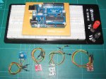
Keine Widerstände nur die Freeimu anschliessen ,die Imu hat alles drauf, 5 volt -minus -scl-sda.


/* This option should be uncommented if ACC Z is accurate enough when motors are running*/
/* should now be ok with BMA020 and BMA180 ACC */
#define TRUSTED_ACCZ

Das kannste Rausnehmen ,hast ja jetzt Imu


#define I2C_SPEED 100000L //100kHz normal mode, this value must be used for a genuine WMP
//#define I2C_SPEED 400000L //400kHz fast mode, it works only with some WMP clones

Auf 400hz setzen

Das kann man nehmen ,muss man aber nicht . Ich hab ihn auf 6-8 gesetzt.

/* introduce a deadband around the stick center
Must be greater than zero, comment if you dont want a deadband on roll, pitch and yaw */
//#define DEADBAND 6

Den Filter kann man setzen muss man aber nicht,ich hab ihn auf 42 hz. bei 3.7 auf Roll und Pitch.

Ohne Filter muss ich so ca. 8-9 Roll und Pitch stellen.

/* MPU6050 Low pass filter setting. In case you cannot eliminate all vibrations to the Gyro, you can try
to decrease the LPF frequency, only one step per try. As soon as twitching gone, stick with that setting.
It will not help on feedback wobbles, so change only when copter is randomly twiching and all dampening and
balancing options ran out. Uncomment only one option!
IMPORTANT! Change low pass filter setting changes PID behaviour, so retune your PID's after changing LPF.*/
//#define MPU6050_LPF_256HZ // This is the default setting, no need to uncomment, just for reference
//#define MPU6050_LPF_188HZ
//#define MPU6050_LPF_98HZ
//#define MPU6050_LPF_42HZ
//#define MPU6050_LPF_20HZ
//#define MPU6050_LPF_10HZ // Use this only in extreme cases, rather change motors and/or props


Hier noch von Alex aus dem Multiwii Forum:
http://www.multiwii.com/faq#Starting_running_amp_stopping_MultiWii


Starting, running & stopping MultiWii

The motors do not start

Move the rudder full right with throttle all the way down to start the motors, full left to turn off the motors.
If the LED stays off, it is a problem related to the RX setup.
If the LED is going ON after the arming procedure, it is a problem related to the ESCs.

The motors still do not start or start but do not stop any more

You have to adjust the travel of your channels so it has a range from 1000 to 2000 on the GUI.
Most likely you need to extend your channel endpoints on your transmitter so the minimum & maximum request is changing from 1000 to 2000.
For Graupner/JR radio, it implies an ATV of 125% for all channels.
On most radios, the endpoints or travel adjusts must be increased to approximately 120% till140%. to get a 1000 to 2000 range in the GUI.
If this range is not matched, the arming level value can’t be reached on the yaw channel, and it’s not possible to arm the motors.
Before trying to operate the MultiWii copter, it’s important to set the end points with the help of the GUI.

The motors still do not start, what about the minimum throttle signal send to the ESC’s

In some cases the ESC’s do not start with the supplied standard minimum throttle value.
It’s possible to lower this value in order to start the ESC’s.
One can try to lower the MINCOMMAND value with steps of 50 to 950 or 900.

The motors start & stop but after trimming the yaw it’s no longer possible to start or stop the motors

By setting the trim, the complete range moves up or down so the endpoint does not reach the desired 1000 or 2000 any more.
One transmitter suffering from this is e.g. the very basic Planet T5 2.4Ghz transmitter.

Be sure your ESC can support PPM with 490Hz refresh rate

For the MultiWii we need a fast update rate & ESC’s which can handle that.
There are a number of standard ESCs than can handle update rates of about 490 Hz, namely Turnigy Plush, Mystery Blue, HK SS and a few others.
The 490Hz basically means that the ESC gets 490 times per second an update.
A standard servo for example works at 50hz or is updated 50 times per second.

Here is a diagram with the different frequencies used in the MultiWii project

Why is it important to define the minimum running value for the ESCs ?

The motors should always run whatever the situation in flight:
•ESCs and motors are not perfect and does not synchronize every time at the beginning. If this happens in the air, one motor won’t be able to spin and I let you imagine the situation.
•Gyro-induced corrections can put a ESC in a situation where it is under its running limit (motor stop). It should not be important because it lasts a fraction of second and propellers have some inertia. But I observed a very annoying behavior with Turnigy Plush ESCs: once it is below the running limit, the ESC reaction time to return into the running range is very high, causing crashing oscillations.

If you choose another ESC, you have to tweak this “minimum spinning value”.
The value depends also of the way the ESCs ware calibrated.
Once armed, if the motors are not running, this value must be changed.
This parameter is very important and has to be edited to compile arduino code.
It is one of the key to have a stable multicopter in descent.

One motor stops suddenly in a flight

It may occur if your ESC is configured in soft mode.
It is preferable to set the ESCs in MEDIUM or HIGH mode.
A simple test to check this problem:
- hold the multicopter firmly in your hand
- start the motors and put a little throttle (enough to feel the gyro correction)
- shake it to counter the motor reaction
- if one motor stops, the problem is then related to motor-ESC combination and you probably need to adjust the timing

Und wech
 
Zuletzt bearbeitet:

kalle123

Jugend forscht ....
#24
Ich hatte dir empfohlen, dir nen arduino uno zu besorgen und mit einem "fliegenden" Aufbau zu probieren, was mit dem WMP los ist. Und du hast eine Referenz zum pro mini.

So nun hast du 84 € auf den Tisch gelegt und kommst auch nicht weiter.

Weiss nicht, wie ich dir weiter helfen kann :confused:

Gruß KH
 
#25
@Desaster:

Hab die Widerstände weg und die conf so geändert wie du geschrieben hast. Geht nichts! zum ko... ist das. Naja wir werden weiter probieren.

Danke auf jeden Fall mal!!!

@Kalle:

Wenn die Lieferung vom fernen Osten etwas schneller wäre, wäre der Uno schon längst da. Kennst das ja :) Aber es soll ja nicht heißen, das die 84 Euronen um sonst waren. Ich denke nicht da dieser Quad der erste und letzte sein wird! :)

mfg MH
 

kalle123

Jugend forscht ....
#26
Mamba, lass den Kopf nicht hängen.

So sieht mein "Elektronikprüfstand" aus. ;)

Dünne Litze am Sensor (ROT +, SCHWARZ GND, GELB SLC, GRÜN SDA) mit Stiften dran.

So sind ev. Fehler viel einfacher zu finden, als wenn du alles auf dem shield zusammengelötet hast.
(Der pro mini mit FTDI Schnittstelle auf nem shield ist alles andere als ideal, um Fehler aufzuspüren.)

(Hab mir einmal einen MS5611 geschrottet, aber da hab ich nicht aufgepasst und den statt an 3.3V an 5V am uno angeschlossen)

Muss auch noch auf meinen 2.ten uno warten. Der liegt seit 2 Wochen beim Zoll in Ffm. :(

Wenn es wie in deinem Fall eilt, hätte ich eher hier zugegriffen.
http://www.ebay.de/itm/DE-Versand-S...=Wissenschaftliche_Geräte&hash=item27c40115f5

Gruß KH
 

Anhänge

#27
Servus Kalle,

ich hab mir heut in der Bucht einen geschossen. Der andere war noch nicht mal verschickt. Hab dort ne Mail hinterlassen und storniert. Ich hoffe das Ding kommt noch diese Woche. Kann ich den ProMini da auch testen???

mfg MH
 

kalle123

Jugend forscht ....
#28
#29
Servus Leuts,

ich greif den Thread mal wieder auf. Ich hatte jetzt mal wieder Zeit um an dem Copter zu basteln. Er wäre jetzt weitgehenst flugbereit, wenn die Software jetzt endlich mal funzen würde!!

Ich hab mir jetzt die 2.0er draufgespielt. Hab meines Erachtens nach alles richtig drin und es geht ums verrecken nicht. Ich bekomm in der GUI immer noch nichts angezeigt. Das komische ist: wenn ich in der GUI auf Start drücke, blinkt an meinem FTDI nur die rote LED, die grüne nicht. Bei nem Kollegen haben wir den FTDI getestet und da funzt das Ding. Also kann es nicht daran liegen. Hat jemand nen funktionierenden Sketch mit dieser Hardware (FreeImu, Arduino Pro Mini 328) und würde mir den zum testen mal zur Verfügung stellen?!? Wäre oberklasse. Ich zweifel so langsam an mir selbst....

Danke und Gruß
M.H.
 

FireN

trägt sonst keine Brille!
#30
wieso benutzt du nicht 2.1?
 
#31
Meinst da funktionierts???

Ich glaube es nicht. Aber ich kanns versuchen. Es hat bei der 1.8er schon nicht getan, bei der 2.0er auch nicht, dann wäre die Wunderwaffe jetzt die 2.1er :)

mfg

M.H
 

FireN

trägt sonst keine Brille!
#32
Ein Versuch ist es auf jeden fall wert, ich schätze Regler eingelernt (einzeln) und mit minthrottle hast du schon rumgespielt?
 
#33
Regler sind eingelernt, Minthrottle ist eingestellt. Also es ist Ruhe wenn ich den Copter an den Akku hänge. Wenn mir die GUI mal was anzeigen würde, wäre mir schon sehr geholfen. Ich versuch die 2.1er jetzt mal noch kurz..

mfg

Also 2.1er drauf. In der GUI erscheint jetzt mal ne braune Linie, aber mehr auch nicht. Keine Reaktion auf Knüppelwege etc. Was ich geändert habe in der config hänge ich unten ran.

Und die Grüne LED auf dem Arduino blinkt fröhlich vor sich hin. Das hat sie bei der 2.0er nicht getan. Da fing sie erst an mit blinken als ich den Copter geneigt habe....

****//#define GIMBAL
****//#define BI
****//#define TRI
****//#define QUADP
****#define*QUADX
****//#define Y4
****//#define Y6
****//#define HEX6
****//#define HEX6X
****//#define OCTOX8
****//#define OCTOFLATP
****//#define OCTOFLATX
****//#define FLYING_WING
****//#define VTAIL4
****//#define AIRPLANE
****//#define SINGLECOPTER
****//#define DUALCOPTER
****//#define HELI_120_CCPM
****//#define HELI_90_DEG

**/**************************** Motor minthrottle *******************************/
****/* Set the minimum throttle command sent to the ESC (Electronic Speed Controller)
*******This*is*the*minimum*value*that*allow*motors*to*run*at*a*idle*speed***/
****//#define MINTHROTTLE 1300 // for Turnigy Plush ESCs 10A
****//#define MINTHROTTLE 1120 // for Super Simple ESCs 10A
****//#define MINTHROTTLE 1064 // special ESC (simonk)
****#define*MINTHROTTLE*1050

**/**************************** Motor maxthrottle *******************************/
****/* this is the maximum value for the ESCs at full power, this value can be increased up to 2000 */
******#define*MAXTHROTTLE*1850

**/**************************** Mincommand *******************************/
****/* this is the value for the ESCs when they are not armed
*******in*some*cases,*this*value*must*be*lowered*down*to*900*for*some*specific*ESCs,*otherwise*they*failed*to*initiate**/
******#define*MINCOMMAND**950

**/********************************** I2C speed ************************************/
****//#define I2C_SPEED 100000L //100kHz normal mode, this value must be used for a genuine WMP
****#define*I2C_SPEED*400000L***//400kHz fast mode, it works only with some WMP clones

**/*************************** Internal i2c Pullups ********************************/
****/* enable internal I2C pull ups (in most cases it is better to use external pullups) */
****//#define INTERNAL_I2C_PULLUPS

**/**************************************************************************************/
**/***************** boards and sensor definitions ******************/
**/**************************************************************************************/

****/*************************** Combined IMU Boards ********************************/
******/* if you use a specific sensor board:
*********please*submit*any*correction*to*this*list.
***********Note*from*Alex:*I*only*own*some*boards,*for*other*boards,*I'm*not*sure,*the*info*was*gathered*via*rc*forums,*be*cautious**/
******//#define FFIMUv1 // first 9DOF+baro board from Jussi, with HMC5843 <- confirmed by Alex
******//#define FFIMUv2 // second version of 9DOF+baro board from Jussi, with HMC5883 <- confirmed by Alex
******//#define FREEIMUv1 // v0.1 & v0.2 & v0.3 version of 9DOF board from Fabio
******//#define FREEIMUv03 // FreeIMU v0.3 and v0.3.1
******//#define FREEIMUv035 // FreeIMU v0.3.5 no baro
******//#define FREEIMUv035_MS // FreeIMU v0.3.5_MS <- confirmed by Alex
******//#define FREEIMUv035_BMP // FreeIMU v0.3.5_BMP
******//#define FREEIMUv04 // FreeIMU v0.4 with MPU6050, HMC5883L, MS561101BA <- confirmed by Alex
******#define*FREEIMUv043*****// same as FREEIMUv04 with final MPU6050 (with the right ACC scale)
 

FireN

trägt sonst keine Brille!
#34
hmm, braune linie ist ja schonmal ein zeichen...nur was für eins? Ich kenne mich leider auch nicht so gut aus und muss auch bald schlafen, aber ich habe das gefunden: http://fpv-community.de/showthread.php?8485-MultiwiiConf-gibt-keine-Werte-aus
vllt hilft es dir?
ansonsten konnte man bei google noch was finden wenn man nach multiwiiconf keine werte oder zeigt nix an usw sucht.

Hoffe du kriegst das noch hin, jeder weiß ja wie nervig sowas sein kann wenn man nicht weiß woran es liegt :confused: :rolleyes:
 

weisseruebe

Erfahrener Benutzer
#35
Hm. Mit MultiWii hast Du dir eine FC ausgesucht, bei der man ohne ein wenig tieferen Einstieg (und Spaß daran) in die Materie bei Problemen nicht mehr weiter kommt.
1. Kannst Du mit "Read" in der Software PID-Werte auslesen, nach "Start"?

Ich vermute, dass bei Dir schon die Kommunikation mit der FC nicht funktioniert. Um erstmal sicherzustellen, dass das geht, würde ich mal ein ganz einfaches Sketch auf die FC spielen, das einfach die ganze Zeit ein Zeichen sendet.
Z.B. das Blink sketch etwas abwandeln.
---------------
/*
Blink
Turns on an LED on for one second, then off for one second, repeatedly.

This example code is in the public domain.
*/

// Pin 13 has an LED connected on most Arduino boards.
// give it a name:
int led = 1;

// the setup routine runs once when you press reset:
void setup() {
// initialize the digital pin as an output.
pinMode(led, OUTPUT);
Serial.begin(115200);
}

// the loop routine runs over and over again forever:
void loop() {
digitalWrite(led, HIGH); // turn the LED on (HIGH is the voltage level)
delay(1000); // wait for a second
digitalWrite(led, LOW); // turn the LED off by making the voltage LOW
delay(1000); // wait for a second
Serial.println("TEST");
}
-----------------

Das lädst Du mal hoch. Danach gehst Du in das eingebaute Terminal (Die Lupe rechts oben in Arduino), stellst dort als Baudrate auch 115200 ein und sollest nun jede Sekunde "TEST" empfangen vom Arduino.

Wenn das nicht geht: FTDI-Treiber installiert? Richtigen Com-Port gewählt? RX/TX korrekt?

Wenn das funktioniert, sollte man auch ohne Sensor die PID-Werte lesen und schreiben können, wenn die MWC-Software auf der FC ist.

Wenn das alles funktioniert, dann kann man sich über Sensoren Gedanken machen.
 
#36
Moin zusammen,

also hab das Sketch mal geflasht, Geht auch ohne Probs. Nur zeigt er mir keinen "Test" sondern das hier:"fæ˜fæ". Aber im Sekundentakt!

mfg

MH

edit: Ich schmeiss mich gleich wech: hab als Ausgabe gerade nicht "Test" sonder "ar..loch" eingegeben. Geflasht und der Copter fängt im Sekundentakt an zu piepen (ER fühlt sich wohl angesprochen *ggggggg*!!!) In der Ausgabe schreibt er aber auch noch was :)
 

weisseruebe

Erfahrener Benutzer
#39
Da ist irgendwas sehr merkwürdig, aber die Infos zu spärlich, um weitere Ideen zu entwickeln. Wenn nichtmal die Übertragung auf der Schnittstelle klappt...dann weiss ich auch nicht so recht weiter. Ich würde sagen: Forschen ;-) Erstmal die serielle Übertragung hinbekommen, dann weitersehen. Dafür gibt es ja in der Arduino-Welt genügend Tutorials.

Wenn dazu noch alle(?) Motoren piepsen, keine Ahnung. Einen Motor kann man ja vielleicht erklären, wenn der am LED-Pin hängt (bzw. dessen ESC). Aber alle???
 
#40
Moin,

kleines Erfolgserlebnis!Wenn ich die Baudrate auf 57600 stelle, bekomme ich die Ausgabe "TEST" *freu* nun werd ich mal weiter probieren. Ich denke ich muss im Sketch dann die Übertragungsrate auch auf 57600 stellen, oder? Im Gerätemanager steht sie grad noch bei 115200 (auf dem Pc!) Ich forsche weiter :)

to be continued :)
 
FPV1

Banggood

Oben Unten