
WiiCopter - Allgemeine Fragen, Probleme, Links, News
- Themenstarter Grandcaravan
- Beginndatum
Hallo
Bin am WE das erste mal abgehoben. Kann mir einer sagen was der genaue Unterschied zwischen Heat-holding uns acc ist. Im head-holding-Mode konnt ich ihn so halbwegs hin trimmen. Nach dem Umschalten auf acc passierte nichts. In der GUI kann ich es mit der Funke umschalten.
Danke und Gruß
Thomas
Bin am WE das erste mal abgehoben. Kann mir einer sagen was der genaue Unterschied zwischen Heat-holding uns acc ist. Im head-holding-Mode konnt ich ihn so halbwegs hin trimmen. Nach dem Umschalten auf acc passierte nichts. In der GUI kann ich es mit der Funke umschalten.
Danke und Gruß
Thomas
Danke heckmic.
Wenn ich das richtig verstehe richtet sich der Kopter im head-holding-Modus-ohne Knüppelbewegung auf, während er im acc-Modus die letzte Fluglage beibehält die er per Steuerbefehl bekommen hat. Werde das sobald wie möglich ausprobieren. Auch die Links die unten drunter standen waren hilfreich (PID etc.) .
Danke Thomas
") - Bitteschön
- BitteschönProblemer Crius SE Multiwii 2.0
Hallo Leute,
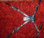
ich habe mir ein spider aufgebaut
die version 2.0 aufgespielt
und das crius board se im sketch ausgewählt
und den kompass kalibriert.
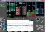
im anhang mal 2 bilder
der copter fliegt ziemlich bescheiden
ich habe schon viele einstellungen versucht
ob im normal modus oder im level modus der copter zuckt, lässt sich nur mit etwas mühe stabilisieren.
könnt ihr mal auf die einstellungen schauen ob da etwas nicht stimmt?
vielen dank schon einmal
gruss
andy
Hallo Leute,
ich habe mir ein spider aufgebaut
die version 2.0 aufgespielt
und das crius board se im sketch ausgewählt
und den kompass kalibriert.
im anhang mal 2 bilder
der copter fliegt ziemlich bescheiden
ich habe schon viele einstellungen versucht
ob im normal modus oder im level modus der copter zuckt, lässt sich nur mit etwas mühe stabilisieren.
könnt ihr mal auf die einstellungen schauen ob da etwas nicht stimmt?
vielen dank schon einmal
gruss
andy
Code:
/*************************************************************************************************/
/****           CONFIGURABLE PARAMETERS                                                       ****/
/*************************************************************************************************/
/* Set the minimum throttle command sent to the ESC (Electronic Speed Controller)
   This is the minimum value that allow motors to run at a idle speed  */
//#define MINTHROTTLE 1300 // for Turnigy Plush ESCs 10A
//#define MINTHROTTLE 1120 // for Super Simple ESCs 10A
//#define MINTHROTTLE 1220
#define MINTHROTTLE 1150
/* The type of multicopter */
//#define GIMBAL
//#define BI
//#define TRI
//#define QUADP
#define QUADX
//#define Y4
//#define Y6
//#define HEX6
//#define HEX6X
//#define OCTOX8
//#define OCTOFLATP
//#define OCTOFLATX
//#define FLYING_WING
//#define VTAIL4
#define YAW_DIRECTION 1 // if you want to reverse the yaw correction direction
//#define YAW_DIRECTION -1
//#define I2C_SPEED 100000L     //100kHz normal mode, this value must be used for a genuine WMP
#define I2C_SPEED 400000L   //400kHz fast mode, it works only with some WMP clones
//enable internal I2C pull ups
//#define INTERNAL_I2C_PULLUPS

//****** advanced users settings   ****************************************
/* ===================================================================== */
/* I2C DFRobot LED RING communication */
//#define LED_RING
/* This option should be uncommented if ACC Z is accurate enough when motors are running*/
/* should now be ok with BMA020 and BMA180 ACC */
#define TRUSTED_ACCZ
/* This will activate the ACC-Inflight calibration if unchecked */
//#define InflightAccCalibration
/* PIN A0 and A1 instead of PIN D5 & D6 for 6 motors config and promini config
   This mod allow the use of a standard receiver on a pro mini
   (no need to use a PPM sum receiver)
*/
//#define A0_A1_PIN_HEX
/* possibility to use PIN8 or PIN12 as the AUX2 RC input
   it deactivates in this case the POWER PIN (pin 12) or the BUZZER PIN (pin 8)
*/
//#define RCAUXPIN8
#define RCAUXPIN12
/* GPS using a SERIAL port
   only available on MEGA boards (this might be possible on 328 based boards in the future)
   if enabled, define here the Arduino Serial port number and the UART speed
   note: only the RX PIN is used, the GPS is not configured by multiwii
   the GPS must be configured to output NMEA sentences (which is generally the default conf for most GPS devices)
   uncomment the first line to select the GPS serial port of the arduino */
//#define GPS_SERIAL 2 // should be 2 for flyduino v2. It's the serial port number on arduino MEGA
#define GPS_BAUD   115200
/* I2C GPS device made with an independant arduino + GPS device
   including some navigation functions
   contribution from EOSBandi
   [URL]http://code.google.com/p/i2c-gps-nav/[/URL] */
//#define I2C_GPS
/* GPS data readed from Misio-OSD  ( EXPERIMENTAL )
   If we have Misio-OSD with GPS module connected to OSD we can use this GPS for navigation purpose.
   Working with OSD firmware v0.66 or newer.
   contribution from Mis */
//#define GPS_FROM_OSD
/* Pseudo-derivative conrtroller for level mode (experimental)
   Additional information: [URL]http://www.multiwii.com/forum/viewtopic.php?f=8&t=503[/URL] */
//#define LEVEL_PDF
/* introduce a deadband around the stick center
   Must be greater than zero, comment if you dont want a deadband on roll, pitch and yaw */
//#define DEADBAND 6
/* interleaving delay in micro seconds between 2 readings WMP/NK in a WMP+NK config
   if the ACC calibration time is very long (20 or 30s), try to increase this delay up to 4000
   it is relevent only for a conf with NK */
#define INTERLEAVING_DELAY 3000
/* when there is an error on I2C bus, we neutralize the values during a short time. expressed in microseconds
   it is relevent only for a conf with at least a WMP */
#define NEUTRALIZE_DELAY 100000
/********************************************************************/
/****           boards and sensor definitions                    ****/
/********************************************************************/
/* if you use a specific sensor board:
   please submit any correction to this list.
     Note from Alex: I only own some boards
                     for other boards, I'm not sure, the info was gathered via rc forums, be cautious */
//#define FFIMUv1         // first 9DOF+baro board from Jussi, with HMC5843                   <- confirmed by Alex
//#define FFIMUv2         // second version of 9DOF+baro board from Jussi, with HMC5883       <- confirmed by Alex
//#define FREEIMUv1       // v0.1 & v0.2 & v0.3 version of 9DOF board from Fabio
//#define FREEIMUv03      // FreeIMU v0.3 and v0.3.1
//#define FREEIMUv035     // FreeIMU v0.3.5 no baro
//#define FREEIMUv035_MS  // FreeIMU v0.3.5_MS                                                <- confirmed by Alex
//#define FREEIMUv035_BMP // FreeIMU v0.3.5_BMP
//#define FREEIMUv04      // FreeIMU v0.4 with MPU6050, HMC5883L, MS561101BA                  <- confirmed by Alex
//#define FREEIMUv043     // same as FREEIMUv04 with final MPU6050 (with the right ACC scale)
//#define PIPO            // 9DOF board from erazz
//#define QUADRINO        // full FC board 9DOF+baro board from witespy  with BMP085 baro     <- confirmed by Alex
//#define QUADRINO_ZOOM   // full FC board 9DOF+baro board from witespy  second edition       <- confirmed by Alex
//#define ALLINONE        // full FC board or standalone 9DOF+baro board from CSG_EU
//#define AEROQUADSHIELDv2
//#define ATAVRSBIN1      // Atmel 9DOF (Contribution by EOSBandi). requires 3.3V power.
//#define SIRIUS          // Sirius Navigator IMU                                             <- confirmed by Alex
//#define SIRIUS600       // Sirius Navigator IMU  using the WMP for the gyro
//#define MINIWII         // Jussi's MiniWii Flight Controller
//#define CITRUSv2_1      // CITRUS from qcrc.ca
//#define CHERRY6DOFv1_0
//#define DROTEK_10DOF    // Drotek 10DOF with ITG3200, BMA180, HMC5883, BMP085, w or w/o LLC
//#define DROTEK_10DOF_MS // Drotek 10DOF with ITG3200, BMA180, HMC5883, MS5611, LLC
//#define DROTEK_6DOFv2   // Drotek 6DOF v2
//#define DROTEK_6DOF_MPU // Drotek 6DOF with MPU6050
//#define MONGOOSE1_0     // mongoose 1.0    [URL]http://www.fuzzydrone.org/[/URL]
//#define CRIUS_LITE      // Crius MultiWii Lite
#define CRIUS_SE        // Crius MultiWii SE
//if you use independent sensors
//leave it commented if you already checked a specific board above
/* I2C gyroscope */
//#define ITG3200
//#define L3G4200D
/* I2C accelerometer */
//#define MMA745
//#define ADXL345
//#define BMA020
//#define BMA180
//#define NUNCHACK  // if you want to use the nunckuk as a standalone I2C ACC without WMP
//#define LIS3LV02
//#define LSM303DLx_ACC
/* I2C barometer */
//#define BMP085
//#define MS561101BA
/* I2C magnetometer */
//#define HMC5843
//#define HMC5883
//#define AK8975
//#define MAG3110
/* ADC accelerometer */ // for 5DOF from sparkfun, uses analog PIN A1/A2/A3
//#define ADCACC
/* ITG3200 & ITG3205 Low pass filter setting. In case you cannot eliminate all vibrations to the Gyro, you can try
   to decrease the LPF frequency, only one step per try. As soon as twitching gone, stick with that setting.
   It will not help on feedback wobbles, so change only when copter is randomly twiching and all dampening and
   balancing options ran out. Uncomment only one option!
   IMPORTANT! Change low pass filter setting changes PID behaviour, so retune your PID's after changing LPF.*/
//#define ITG3200_LPF_256HZ     // This is the default setting, no need to uncomment, just for reference
//#define ITG3200_LPF_188HZ
//#define ITG3200_LPF_98HZ
//#define ITG3200_LPF_42HZ
//#define ITG3200_LPF_20HZ
//#define ITG3200_LPF_10HZ      // Use this only in extreme cases, rather change motors and/or props
/* MPU6050 Low pass filter setting. In case you cannot eliminate all vibrations to the Gyro, you can try
   to decrease the LPF frequency, only one step per try. As soon as twitching gone, stick with that setting.
   It will not help on feedback wobbles, so change only when copter is randomly twiching and all dampening and
   balancing options ran out. Uncomment only one option!
   IMPORTANT! Change low pass filter setting changes PID behaviour, so retune your PID's after changing LPF.*/
//#define MPU6050_LPF_256HZ     // This is the default setting, no need to uncomment, just for reference
//#define MPU6050_LPF_188HZ
//#define MPU6050_LPF_98HZ
//#define MPU6050_LPF_42HZ
//#define MPU6050_LPF_20HZ
//#define MPU6050_LPF_10HZ      // Use this only in extreme cases, rather change motors and/or props
/* GYRO_SMOOTHING. In case you cannot reduce vibrations _and_ _after_ you have tried the low pass filter options, you
   may try this gyro smoothing via averaging. Not suitable for multicopters!
   Good results for helicopter, airplanes and flying wings (foamies) with lots of vibrations.*/
//#define GYRO_SMOOTHING {20, 20, 3}    // separate averaging ranges for roll, pitch, yaw
// Moving Average Gyros by Magnetron1 (Michele Ardito) ########## beta
//#define MMGYRO                         // Active Moving Average Function for Gyros
//#define MMGYROVECTORLENGHT 10          // Lenght of Moving Average Vector
// Moving Average ServoGimbal Signal Output
//#define MMSERVOGIMBAL                  // Active Output Moving Average Function for Servos Gimbal
//#define MMSERVOGIMBALVECTORLENGHT 32   // Lenght of Moving Average Vector
/*--------------------------------------------------------------------*/
/* Settings for ProMicro, Leonardo and other Atmega32u4 Boards (BETA) */
  // activate this for a better pinlayout if all pins can be used => not possible on ProMicro!
  //#define A32U4ALLPINS
  // activate all 6 hardware PWM outputs Motor 5 = D11 and 6 = D13. => not possible on ProMicro! (untested!)
  // if activated:
  // Motor 1-6 = 10-bit hardware PWM
  // Motor 7-8 = 8-bit Software PWM
  // Servos    = 8-bit Software PWM
  // if deactivated:
  // Motor 1-4 = 10-bit hardware PWM
  // Motor 5-8 = 10-bit Software PWM
  // Servos    = 10-bit Software PWM
  //#define HWPWM6
  // aux2 pin on pin RXO
  //#define RCAUX2PINRXO
  // aux2 pin on pin D17 (RXLED)
  //#define RCAUX2PIND17
  // this moves the Buzzer pin from TXO to D8 for use with ppm sum or spectrum sat. RX (not needed if A32U4ALLPINS is active)
  //#define D8BUZZER
  // Inverted status LED for Promicro ver 10.
  //#define PROMICRO10
/* end of Settings for ProMicro, Leonardo and other Atmega32u4 Boards */
/*--------------------------------------------------------------------*/
/********************************************************************/
/****           motor, servo and other presets                   ****/
/********************************************************************/
/* motors will not spin when the throttle command is in low position
   this is an alternative method to stop immediately the motors */
#define MOTOR_STOP
/* some radios have not a neutral point centered on 1500. can be changed here */
#define MIDRC 1500
/* The following lines apply only for a pitch/roll tilt stabilization system
   Uncomment the first line to activate it */
//#define SERVO_TILT
#define TILT_PITCH_MIN    1020    //servo travel min, don't set it below 1020
#define TILT_PITCH_MAX    2000    //servo travel max, max value=2000
#define TILT_PITCH_MIDDLE 1500    //servo neutral value
#define TILT_PITCH_PROP   10      //servo proportional (tied to angle) ; can be negative to invert movement
#define TILT_ROLL_MIN     1020
#define TILT_ROLL_MAX     2000
#define TILT_ROLL_MIDDLE  1500
#define TILT_ROLL_PROP    10
/* experimental
   camera trigger function : activated via Rc Options in the GUI, servo output=A2 on promini */
//#define CAMTRIG
#define CAM_SERVO_HIGH 2000  // the position of HIGH state servo
#define CAM_SERVO_LOW 1020   // the position of LOW state servo
#define CAM_TIME_HIGH 1000   // the duration of HIGH state servo expressed in ms
#define CAM_TIME_LOW 1000    // the duration of LOW state servo expressed in ms
/* you can change the tricopter servo travel here */
#define TRI_YAW_CONSTRAINT_MIN 1020
#define TRI_YAW_CONSTRAINT_MAX 2000
#define TRI_YAW_MIDDLE 1500 // tail servo center pos. - use this for initial trim; later trim midpoint via LCD
/* Flying Wing: you can change change servo orientation and servo min/max values here */
/* valid for all flight modes, even passThrough mode */
/* need to setup servo directions here; no need to swap servos amongst channels at rx */
#define PITCH_DIRECTION_L 1 // left servo - pitch orientation
#define PITCH_DIRECTION_R -1  // right servo - pitch orientation (opposite sign to PITCH_DIRECTION_L, if servos are mounted in mirrored orientation)
#define ROLL_DIRECTION_L 1 // left servo - roll orientation
#define ROLL_DIRECTION_R 1  // right servo - roll orientation  (same sign as ROLL_DIRECTION_L, if servos are mounted in mirrored orientation)
#define WING_LEFT_MID  1500 // left servo center pos. - use this for initial trim; later trim midpoint via LCD
#define WING_RIGHT_MID 1500 // right servo center pos. - use this for initial trim; later trim midpoint via LCD
#define WING_LEFT_MIN  1020 // limit servo travel range must be inside [1020;2000]
#define WING_LEFT_MAX  2000 // limit servo travel range must be inside [1020;2000]
#define WING_RIGHT_MIN 1020 // limit servo travel range must be inside [1020;2000]
#define WING_RIGHT_MAX 2000 // limit servo travel range must be inside [1020;2000]
/********************************************************************/
/****           powermeter                                       ****/
/********************************************************************/
/===================================================================== */
//if you want to change to orientation of individual sensor
//#define ACC_ORIENTATION(X, Y, Z)  {accADC[ROLL]  =  Y; accADC[PITCH]  = -X; accADC[YAW]  = Z;}
//#define GYRO_ORIENTATION(X, Y, Z) {gyroADC[ROLL] = -Y; gyroADC[PITCH] =  X; gyroADC[YAW] = Z;}
//#define MAG_ORIENTATION(X, Y, Z)  {magADC[ROLL]  = X; magADC[PITCH]  = Y; magADC[YAW]  = Z;}

/* frequenies for rare cyclic actions in the main loop, depend on cycle time! */
/* time base is main loop cycle time - a value of 6 means to trigger the action every 6th run through the main loop */
/* example: with cycle time of approx 3ms, do action every 6*3ms=18ms */
/* value must be [1; 65535] */
#define LCD_TELEMETRY_FREQ 23       // to send telemetry data over serial 23 <=> 60ms <=> 16Hz (only sending interlaced, so 8Hz update rate)
#define LCD_TELEMETRY_AUTO_FREQ 667 // to step to next telemetry page 667 <=> 2s
#define PSENSORFREQ 6               // to read hardware powermeter sensor 6 <=> 18ms
#define VBATFREQ PSENSORFREQ        // to read battery voltage - keep equal to PSENSORFREQ unless you know what you are doing
/*************************************************************************************************/
/****           END OF CONFIGURABLE PARAMETERS                                                ****/
/*******************************************************************
Anhänge
-
 100,8 KB Aufrufe: 8
 -
 98,6 KB Aufrufe: 28
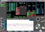
Sieht gut aus.
Kannst du evtl mal n Video vom Flug machen? Das man mal in etwa gucken kann, wo man ansetzen muss.
Kenne deine IMU nicht, da ich nur Drotek IMUs fliege. Dazu kann ich also nix sagen, aber deine Werte sehen gut aus.
Was du noch testen kannst, die Wirkrichtungen der Sensoren.
Siehe hier:
http://fpv-community.de/showthread.php?8516-Copter-Neuling-mit-Sensor-Fragen&p=118038#post118038
Hi Andy!
Auch wenn ich noch Anfänger bin, hab ich 'ne Idee: Wenn das auf dem Bild die Mystery
Fire Dragon 30A Regler sind, dann habe ich die auch. Ich dachte zunächst, dass die nicht
für Quadrocopter geeignet sind, bis ich gemerkt habe, dass die ihre Programmierung
aus irgendwelchen Gründen verloren hatten. Check einfach nochmal, ob Du nicht nur den
Gasweg eingelernt hast, sondern auch Start auf normal und Timing auf high hast ... das hatten
bei mir nämlich die Regler einfach "vergessen".
Gruss
Quansel
edit: da war Chris bzgl. Gaswege schneller ...
Hallo Chris,
die regler wurden schon mal angelernt (gasweg) und gleich eingestellt.
können die den gasweg vergessen?
hier das passende video.
http://www.youtube.com/watch?v=Bklsxl5vuXE
ich habe ebend #define TRUSTED_ACCZ auskommentiert
und habe das gefühl das er tatsächlich ruhiger in der luft liegt
wohl noch längst nicht optimal aber schon besser als vorher
was bewirkt der eintrag denn?
vielen dank schon mal für die schnelle und gute antwort
@ quansel. das werde ich mal ausprobieren danke für den hinweis (ich habe deinen beitrag erst gelesen als ich meinen hier angesendet habe)
gruss
andy
Zuletzt bearbeitet: