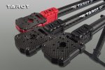
Tarot FY680 C/F Folding Hexacopter

Status
Nicht offen für weitere Antworten.

Cartman

Erfahrener Benutzer
Ein Y6 liegt ganz anders in der Luft. Sehr agil und kaum windanfällig. Sollte man einfach mal ausprobieren. Ich möchte keinen Flat Hexa mehr haben. Die geringere Effizienz fällt kaum auf, weil es in der Praxis nur ein paar Sekunden weniger Flugzeit ausmacht. 3 Ausleger weniger sind schließlich auch eine Gewichtsersparnis und dann hat man beim Y6 noch den Vorteil, dass bei gleichem Durchmesser größere Props passen.

Also einfach mal testen...
 

mane81

MultiCopterPilot
Also wahrscheinlich dann auch ein Y6 bei mir. Habe das klappbare Landegestell dran und muss mir mal ansehen wie ich das am besten um 90 Grad gedreht bekomme….
 

mane81

MultiCopterPilot
Suche nach einer ordentlichen Motor/Propeller-Kombi um eine Nex inkl Gimbal zu heben. Beim Y6 könnte ich ja eventuell 22poler Pancakes mit großen Props nehmen und meine 3S-Akkus weiterverwenden….. !??! Muss mal am eCalc durchchecken….
 
Ein Y6 liegt ganz anders in der Luft. Sehr agil und kaum windanfällig. Sollte man einfach mal ausprobieren. Ich möchte keinen Flat Hexa mehr haben. Die geringere Effizienz fällt kaum auf, weil es in der Praxis nur ein paar Sekunden weniger Flugzeit ausmacht. 3 Ausleger weniger sind schließlich auch eine Gewichtsersparnis und dann hat man beim Y6 noch den Vorteil, dass bei gleichem Durchmesser größere Props passen.

Also einfach mal testen...
1+

Dazu Redundanz und leichtere Orientierung.
Und wenn ich deshalb eine Minute weniger fliege, so be it.
 
Es ist keine gute Idee die ESC's mehr als 200mm von der Batterie entfernt zu haben.
Ich hatte plötzliche Stotterer und unerklärliche Motor ausfälle.
Ich hatte alle moegliche Probleme, und habe dann diesen Bericht gefunden.
Ich habe ihn erst nicht gepostet weil er auf Englisch ist und ich ihn kopiert hatte, aber den Link verloren habe.

Vielleicht hilft es aber trotzdem jemanden:


Well as one who has actually measured the back-emf pulses in battery leads I would have to disagree. I was asked to perform precisely this experiment by an importer last year, because he was being sued by a customer for the cost of four £90 speed controllers (plus consequential damage) that he had fitted into a TN Lanc (the big one). He'd fitted the controllers adjacent to the motors and put the batteries in the bomb bay. 30 seconds into the first flight two of the controllers failed within a couple of seconds of eachother, and the remaining two failed (again within a couple of seconds of eachother) about 10 seonds later as he tried to bring it back. Unfortunately the model went into trees and was a complete write off, damaging several servos and the Rx as well - the customer was claiming a total of £1200.

The instructions supplied with the controllers stated "max battery to lead length 200mm", but the user had used lead lengths of between 800 and 1400mm.

The importer gave me four controllers - one of the original type (a "blue chip" brand, one of another "high cost" brand (Jeti) plus two "budget" ones. All were rated at over 60A, with the budget ones being 100A ratings in deference to their suppliers' advice that they be derated. The tests were conducted at 24v into the controllers using a lead-acid car battery (because I didn't want to wreck a perfectly good lipo should anything fail short-circuit), ramping up to 55A for the tests using an Axi 4120/18 driving a 14-8 prop as the load. Lead lengths from 2000mm to 200mm were used, in 200mm increments plus a few other lengths.

The initial tests were exploratory, setting a notional voltage limit of 100v and finding the shortest lead length at which this voltage was not exceeded at half throttle (starting with the longest lead, testing each controller and then cutting the leads down for the next group of tests - I went through a lot of solder that day!).

It is interesting to note that the observed back-emf pulses were essentially identical with all four controllers, indicating that they all had pretty similar input capacitance. This would suggest that their ability to withstand back-emf pulses was solely down to the characteristics of the MOSFETs used. Tests were observed by the importer and the customer.

From the initial tests we discovered that the longest length at which the back-emf pulses remained below 100v** was around 250-270mm. By inserting additional capacitors we found we could extend this to 500mm and 1000mm, but above that we started getting ringing in the cables so we stopped. We also found that with the additional capacitors fitted there was ringing in the cables if they were short - ie a specific level of capacitance only worked over a specific cable length.

Extended motor runs were then perfomed using each controller at 55Amps for five minutes, demonstrating that the controllers were able to drive the load on 200mm cables.

On the basis of these findings the importer then suggested we try a durability test "to destruction if necessary" with the cables at 800mm and no capacitors. An initial test found that at 55A in this configuration the 1msec pulsewidth was at 430volts. We proceeded to run the test and after 74 seconds (on the original blue-chip controller) the controller vented smoke and died. We then switched to 1400mm cables and repeated the test with the Jeti controller; the pulse voltage was over 700volts and the controller expired after 18 seconds. The tests were repeated with the two budget controllers (one at each cable length) giving numbers of 43 and 14 seconds respectively.

After witnessing the tests the customer withdrew his claim. As a gesture of goodwill the importer decided not to bill the customer for the cost of the controllers consumed, and I then felt that I had to waive my previously agreed fee for the four hours of work

Now every installation is different, and the cable inductance may have bigger effects in some installations than others which is probably why many people have reported "getting away with it". But the 200mm figure is stated by the manufacturers for good reasons, and if you elect to ignore it you're on your own!

£0.02 supplied, YMMV,

PDR

**EMF pulses are not "square"; they are a sharp-edge followed by a decay. Based on advice from the EMH engineer at the office we set this threshold as "the point at which the pulse was above 100v for 1msec" because apparently a 1msec pulse was long enough to damage a MOSFET
 

preloi

Erfahrener Benutzer
Hat jemand die Tarot 4006 620kv mit BlHeli Ecs am laufen.

Ich habe meine Turnigy Plush 25A damit geflasht und habe jetzt massive Syncprobleme.
Egal was ich einstelle in der Firmware, die Motoren laufen nicht richtig.
Gibt es dafür eine angepasste Firmware oder kann man die original Turnigy Firmware irgendwo laden?
 

nurv

Erfahrener Benutzer
hallo Kollegen, ich habe die 4006er Tarot, allerdings passen diese nicht auf die Motorträger. Musst somit diese bestellen. Sobald sie da sind wird wieder weiter gebaut. Als Regler benutze ich die Afro SLIM mit SK - die passen in die Rohre, somit habe ich auch keine Probleme mit dem verlegen der Kabel.
 

Roman.C.

hat zu viele Baustellen
Edit ........
 
Zuletzt bearbeitet:

Jogijo

Erfahrener Benutzer
hallo Kollegen, ich habe die 4006er Tarot, allerdings passen diese nicht auf die Motorträger. Musst somit diese bestellen. Sobald sie da sind wird wieder weiter gebaut. Als Regler benutze ich die Afro SLIM mit SK - die passen in die Rohre, somit habe ich auch keine Probleme mit dem verlegen der Kabel.
Also die Afro Slim würde ich mit den 4006ern besser vorher ausgiebig auf der Werkbank testen, da gibt es einige die von massiven Syncproblemen berichten.
 

roga

Neuer Benutzer
Hallo Kollegen
Da hier mehr los ist und IHR Ahnung habt, frage ich mal hier.
Beim 690s sind die Bohrungen der Motorträger ein wenig versetzt so dass der Motor einen kleinen Anstellwinkel hat (so 2-3 Grad)
OK, das ist ja bei Modellflugzeugen auch so.
Was ich aber nicht verstehe, warum haben alle 6 den Winkel auf die gleiche Seite wo doch drei der Motoren nach links und drei nach rechts drehen.
Kann mir mal einer den Sinn erklären ?
Oder Baut ihr die Motoren alle ohne Winkel ein?

Vielen Dank für etwaige Infos.
 
Vielleicht kannst du mit einem Bild verdeutlichen was du meinst. Ich tippe mal schwer auf einen Fertigungsfehler. Auf den Bildern von Tarot sieht das Ganze eigentlich symmetrisch aus:

FY690 Halterungen.jpg

Gruß,
Chris
 

SteffenS

Erfahrener Benutzer
Nabend,
Bei meinem 690s sind die Ausleger, wie im Bild von Chris, absolut waagerecht zueinander.
Demletzt las ich, glaube hier im Forum, von jemandem, dessen Bohrungen auch gegeneinander versetzt waren. Er bekam es vom Händler ausgetauscht!
Bau mal erst einen Arm aus und stecke durch die Löcher nen großen Zahnstocher. So siehst du, welche versetzt gebohrt sind.

Wo hast du den 690er gekauft?

Gruß
Steffen
 
Hört sich an, wie ein Serienfehler bei der Fertigung. Die Motoren sollten genau senkrecht ausgerichtet sein.
Reklamieren wird kaum was nutzen, am besten feilst du etwas an den Bohrungen.
 

roga

Neuer Benutzer
@steffenS @42Cacher
Ich habe die Löcher ein wenig aufgefräst, so dass die Motorträger gerade stehen da ich sowas in Verdacht hatte.
Nur war ich unsicher, da ich zwei Frames habe und bei BEIDEN die Löcher gleichmäßig versetzt sind, da braucht es keine Zahnstocher, sah man mit freiem Auge.
Ich habe mich eben gewundert weil alle in EINE Richtung gedreht waren und die Motoren nicht alle in die gleiche Richtung laufen.
Wenn keiner von Euich einen Sinn darin sieht, dann bin ich beruhigt und nicht verunsichert ob ich zu blöd bin das zu schnallen warum ;)

DANKE EUCH .
 
Hallo zusammen,
ich suche mür meinen Tarot 680 ein Einziehlandegestell. Dieses Thema wurde hier doch mal diskutiert. gibt es inzwischen eine gut funktionierende Lösung?
Welches System verwendet Ihr?

Schöne Grüße

Jürgen
 

Rheinperchten

Erfahrener Benutzer
Ja ich habe da mal sowas selber gebaut. klappt super. Inzwischen habe ich die etwas ungünstige Verbindung unten von den Beinen zu den Längsfüßen verbessert. nun ist das perfekt stabil.
[video=youtube;EIXYw59-fp4]http://www.youtube.com/watch?v=EIXYw59-fp4[/video]

Ansonsten bleibt nur fertig kaufen,- was aber erheblich teurer und keinesfalls besser ist da teilweise die gleichen Komponenten verwendet werden.
 
Hallo zusammen,

ich habe meinen Tarot mit einziehbarern Beinen von Lipoly ausgestattet. Funktioniert ganz gut und macht auch Spaß!
Das gewicht stieg um ca. 200gr. auf jetzt 3340 Gramm.
Ich hatte vorher im Schwebeflug ca. 30 A, jetzt habe ich 45 A, und das mit nur 200gr. mehr, hat mich ziemlich erstaunt.
Habt Ihr ähnliche Erfahrungen beim Stromanstieg mit relativ geringem Gewichtanstieg gemacht?

Schöne Grüße

Jürgen
 

solution

Erfahrener Benutzer
Neeee, das kann nicht sein! 200 gr machen niemals diese Zunahme an Schwebestrom aus!
Wenn dein Stromwert stimmt, musst du unbedingt herausfinden was da los ist!!! ( Selbst wenn die Servos in den Fahrwerken blockieren sollten kommt man nicht auf den Strom)
Stimmte der Wert vorher?
 
Status
Nicht offen für weitere Antworten.
FPV1

Banggood

Oben Unten